Automated biological reaction apparatus

a biological reaction and automatic technology, applied in the field of biological reaction platforms, can solve the problems of inability to meet the needs of automated, high-precision immunohistology, and limitations in the performance of previously known devices

Inactive Publication Date: 2005-09-13
VENTANA MEDICAL SYST INC
View PDF134 Cites 409 Cited by
  • Summary
  • Abstract
  • Description
  • Claims
  • Application Information

AI Technical Summary

Benefits of technology

[0011]One particular advantageous feature of the present invention is that by employing a computer control arrangement to control the positioning of the reagent and slide support carousel, different reagent treatments can be individually performed for each of the various tissue samples by appropriate programming of the apparatus. Additionally, the provision of the bar code readers permits tracking of each of the tissue samples as well as a record of the reagents applied thereto.
[0019]The stationary slide support has a slide support platform at a proximal end and a slide support post at a distal end thereof. The distal end also has raised lateral distal guide tabs with guide termini between which a slide is positioned. The slide support platform at the proximal end has a guide edge and a slide clamping arrangement for clamping a slide to the support platform without interfering with the reading operation of the bar code reader. The distal guide termini are lower than the upper slide surface plane to prevent wick-off of liquid on the slide surface. In this embodiment, rinse liquid is drained from the surface of the slide employing a jet drain which directs a stream of fluid, i.e., gas or liquid, over the slide surface.

Problems solved by technology

The previously known devices are limited in their performance and unable to satisfy the needs for automated, high precision immunohistology.

Method used


Image

  • Automated biological reaction apparatus
  • Automated biological reaction apparatus
  • Automated biological reaction apparatus

Examples


Embodiment Construction

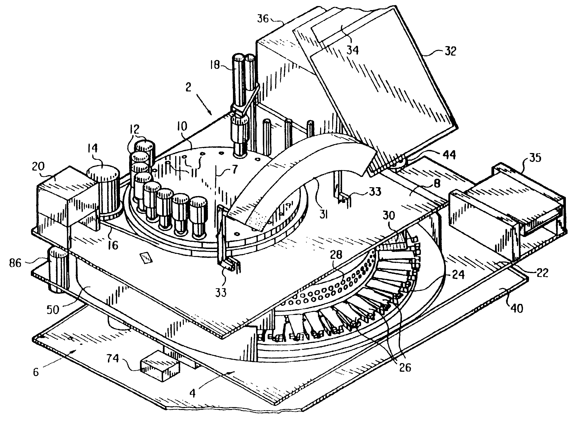
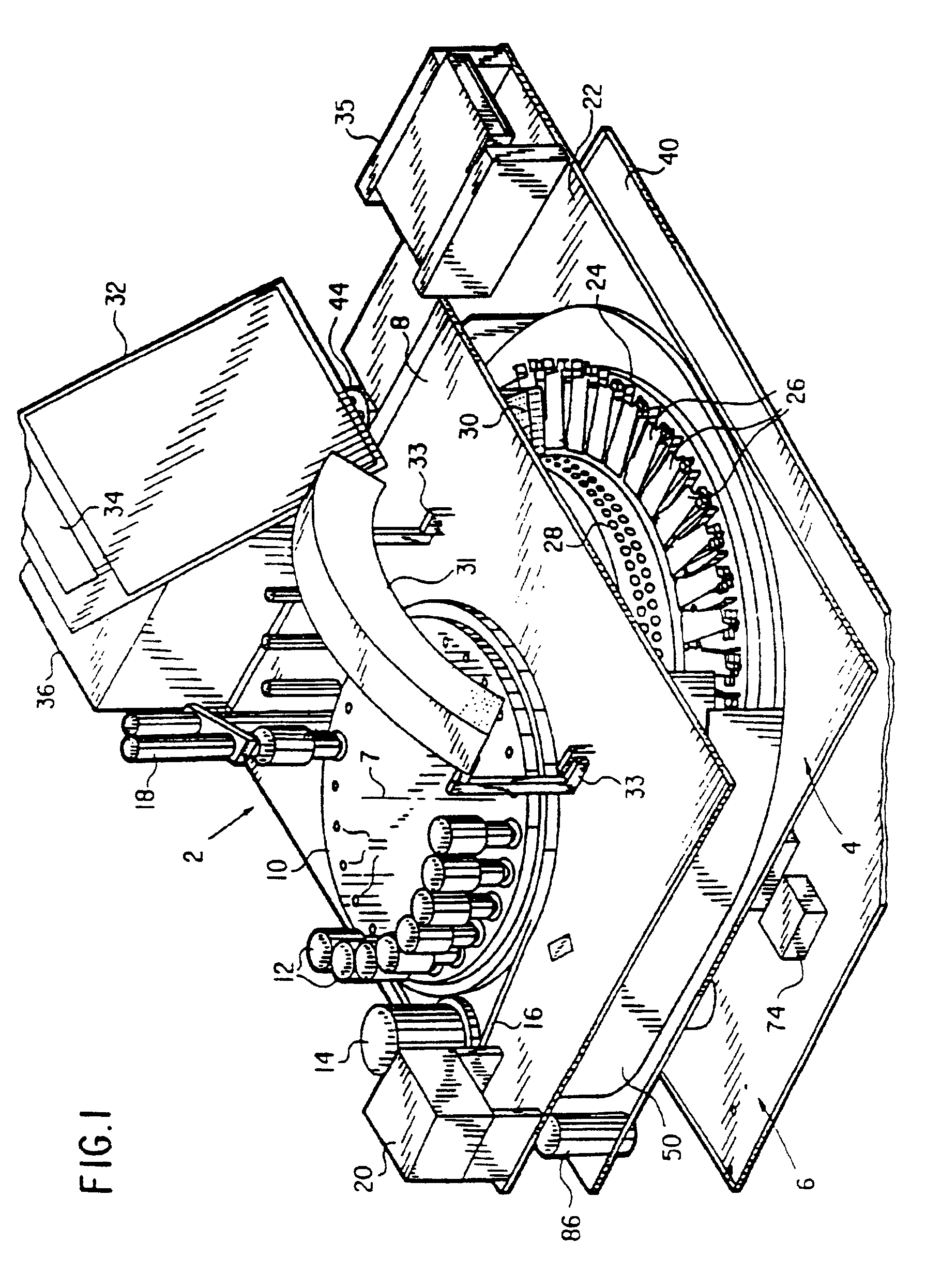
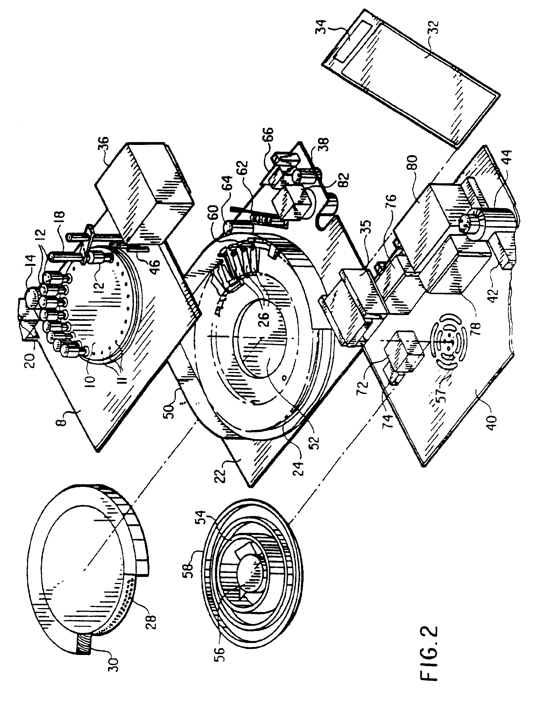
[0058]The automated immunostaining apparatus of this invention preforms all steps of immunohistochemical and in situ DNA assays irrespective of complexity or their order, at the time and temperature, and in the environment needed. Specially prepared slides containing a bar code identifier and a mounted tissue section are placed in special support on a carousel, subjected to a preprogrammed sequence of reactions, and are removed from the carousel, ready for coverslipping and histological examination. For purposes of clarity of the following description of the apparatus of this invention and not by way of limitation, the apparatus will be described in terms of immunohistochemical processes.

[0059]FIG. 1 is a front right, isometric view of the automated immunostaining apparatus of this invention, with the cabinet shell removed. Liquid and air supply tubing and electrical wiring connecting the respective components are conventional, well known in the art, and are omitted from the drawing...


PUM

PropertyMeasurementUnit
temperaturesaaaaaaaaaa
boiling pointaaaaaaaaaa
widthaaaaaaaaaa

Abstract

An automated immunostaining apparatus having a reagent application zone and a reagent supply zone. The apparatus has a carousel slide support supporting a plurality of slide supports thereon, and drive means engaging the carousel slide support for consecutively positioning each of a plurality of slide supports in the reagent application zone. The apparatus also has a carousel reagent support having a plurality of reagent container supports thereon, and drive means engaging the carousel for rotating the carousel and positioning a preselected reagent container support in the reagent supply zone. The apparatus also has a reagent delivery actuator means positioned for engaging a reagent container positioned on a container support in the reagent delivery zone and initiating reagent delivery from the reagent container to a slide supported on a slide support in the reagent receiving zone.

Description

[0001]This is a continuation of application Ser. No. 09 / 452,309, filed on Dec. 1, 1999, now U.S. Pat. No. 6,352,861 which is a continuation of application Ser. No. 08 / 906,678, filed Aug. 5, 1997, abandoned, which is a continuation of application Ser. No. 08 / 479,415, filed Jun. 6, 1995, U.S. Pat. No. 5,654,200, which is a division of application Ser. No. 08 / 352,966, filed Dec. 9, 1994, U.S. Pat. No. 5,595,707, which is a continuation of application Ser. No. 07 / 924,052, filed Aug. 31, 1992, abandoned, which is a continuation-in-part of application Ser. No. 07 / 488,601, filed Mar. 2, 1990, abandoned.TECHNICAL FIELD[0002]This invention relates an improved biological reaction platform which can be used for a wide variety of assays, for example, automatic immunostaining of tissue sections, in situ DNA analysis, immunoassays such as ELISA, and the like. The automatic device of this invention can be used to process a large number of samples such as tissue sections mounted on slide surfaces u...

Claims


Application Information

Patent Timeline
Patent Type & Authority Patents(United States)
IPC IPC(8): B01F13/00B01F13/02B01F5/00G01N1/30G01N1/31G01N35/02G01N35/10G01N35/00B01F33/40
CPCB01F5/0057B01F13/02B01F13/0272G01N1/312G01N35/025G01N35/10G01N35/1002Y10T436/11B01F2215/0037G01N2001/317G01N2035/00079G01N2035/00386G01N2035/00544G01N2035/00752Y10T436/113332Y10T436/114998Y10T436/114165Y10T436/12Y10T436/111666Y10T436/2575Y10T436/25Y10T436/119163Y10T436/112499B01F13/0059B01F25/10B01F33/40B01F33/407B01F33/30B01F2101/23
Inventor COPELAND, KEITH G.GROGAN, THOMAS M.HASSEN, CHARLESHUMPHREYS, WILLIAM ROSSLEMME, CHARLES D.MILLER, PHILLIP C.RICHARDS, WILLIAM L.SHOWALTER, WAYNE A.
Owner VENTANA MEDICAL SYST INC
Why Eureka
Try Eureka