Supercharge Your Innovation With Domain-Expert AI Agents!

Apparatus and method for coding/decoding

a technology of coding/decoding and apparatus, applied in the field of apparatus and method for coding/decoding, can solve the problems of communication quality deterioration and the decline of achieve the effect of improving the error correction decoding performan

Inactive Publication Date: 2005-09-13
III HLDG 12 LLC
View PDF25 Cites 28 Cited by
  • Summary
  • Abstract
  • Description
  • Claims
  • Application Information

AI Technical Summary

Benefits of technology

[0013]It is an object of the present invention to provide a coding / decoding apparatus and a coding / decoding method that is capable of increasing the error correcting decoding performance and thereby improving the communication quality.
[0015]Furthermore, the essence of the present invention is to improve the error correcting decoding performance by dividing data through code block segmentation prior to error correcting coding so that the length of code block data is an integer multiple of the length of transport block data and thereby ensuring that the CRC-bit exists at the end of each code block.

Problems solved by technology

When the receiving side performs error correcting decoding (e.g., turbo decoding), CRC-bit is used as decision criteria, but the CRC-bit that normally exists at the end of a data group does not exist at the end of the first code block as shown above, and therefore there is a problem that the error correcting decoding performance decreases and the communication quality deteriorates.

Method used


Image

  • Apparatus and method for coding/decoding
  • Apparatus and method for coding/decoding
  • Apparatus and method for coding/decoding

Examples


embodiment 1

[0023](Embodiment 1)

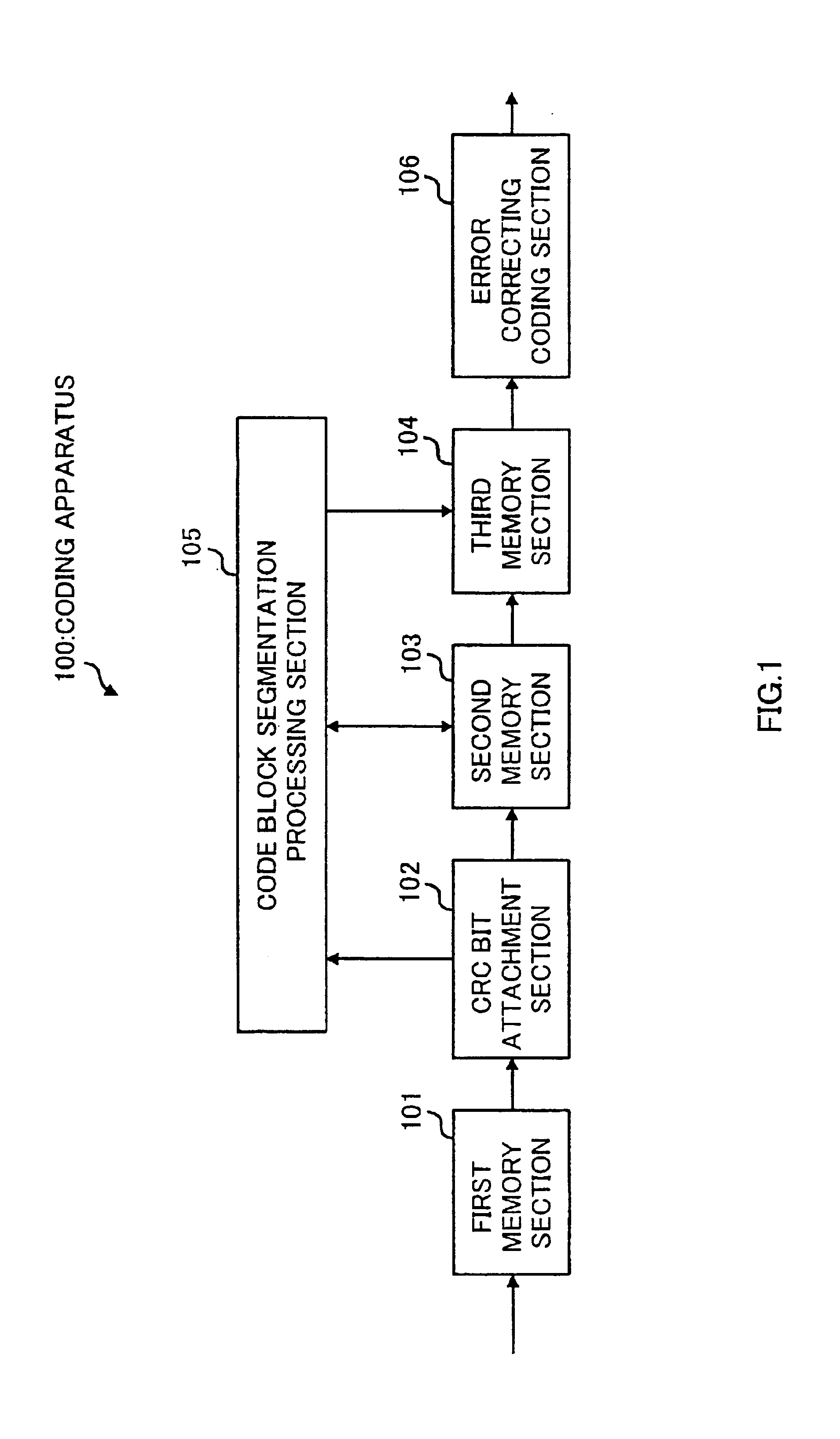
[0024]FIG. 1 is a block diagram showing a configuration of a coding apparatus according to Embodiment 1 of the present invention.

[0025]The coding apparatus 100 shown in FIG. 1 is used as a transmitting means, for instance, of a mobile station apparatus or base station apparatus, and is provided with a first memory section 101, a CRC bit attachment section 102, a second memory section 103, a third memory section 104, a code block segmentation processing section 105, and an error correcting coding section 106.

[0026]The first memory section 101 stores transmission data.

[0027]The CRC bit attachment section 102 adds CRC-bit to the data stored in the first memory section 101 by carrying out CRC coding in transport block units. The data with CRC-bit added is stored in the second memory section 103.

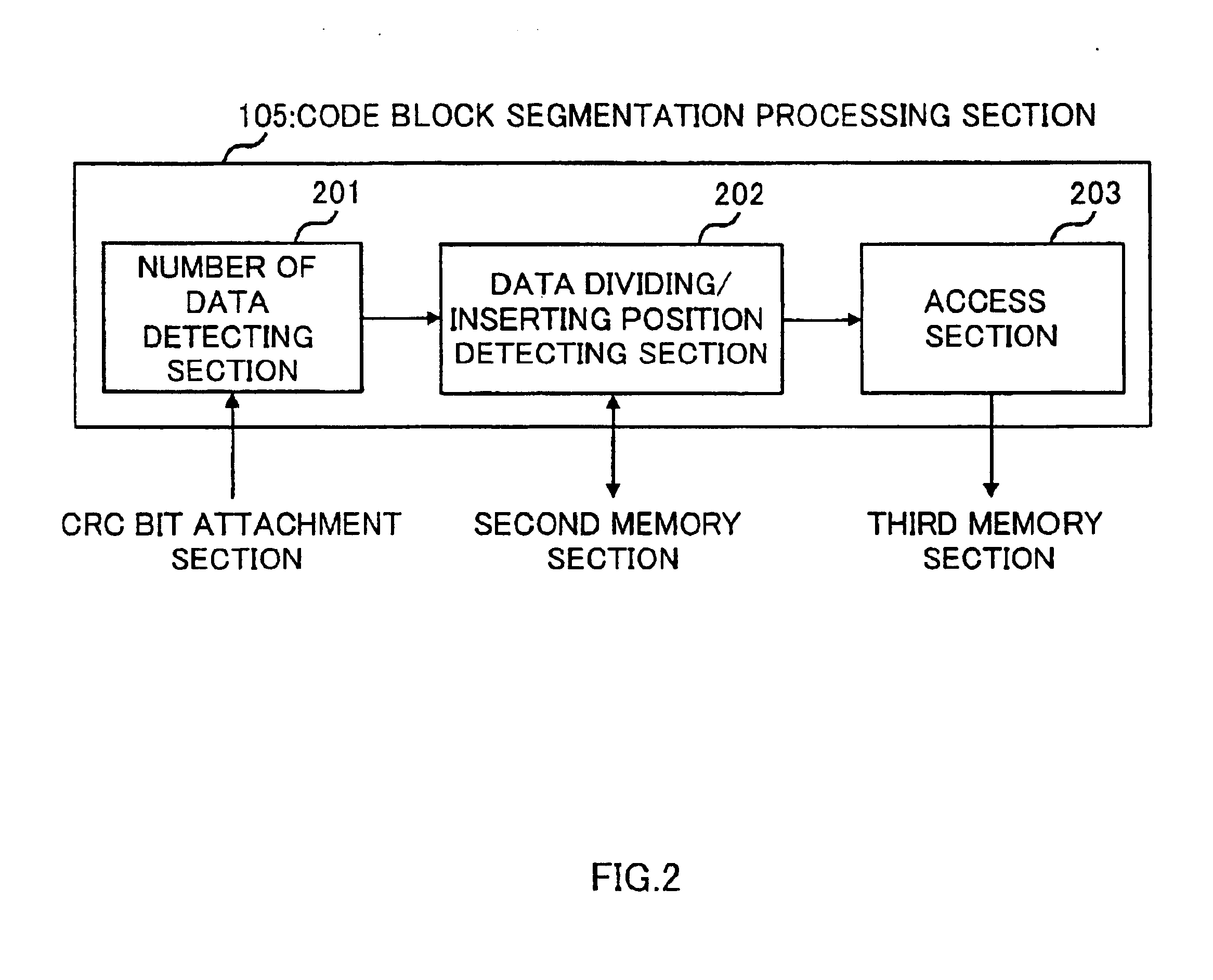
[0028]The code block segmentation processing section 105 is the one that carries out code block segmentation processing and is provided with a number of data detecting section...

embodiment 2

[0043](Embodiment 2)

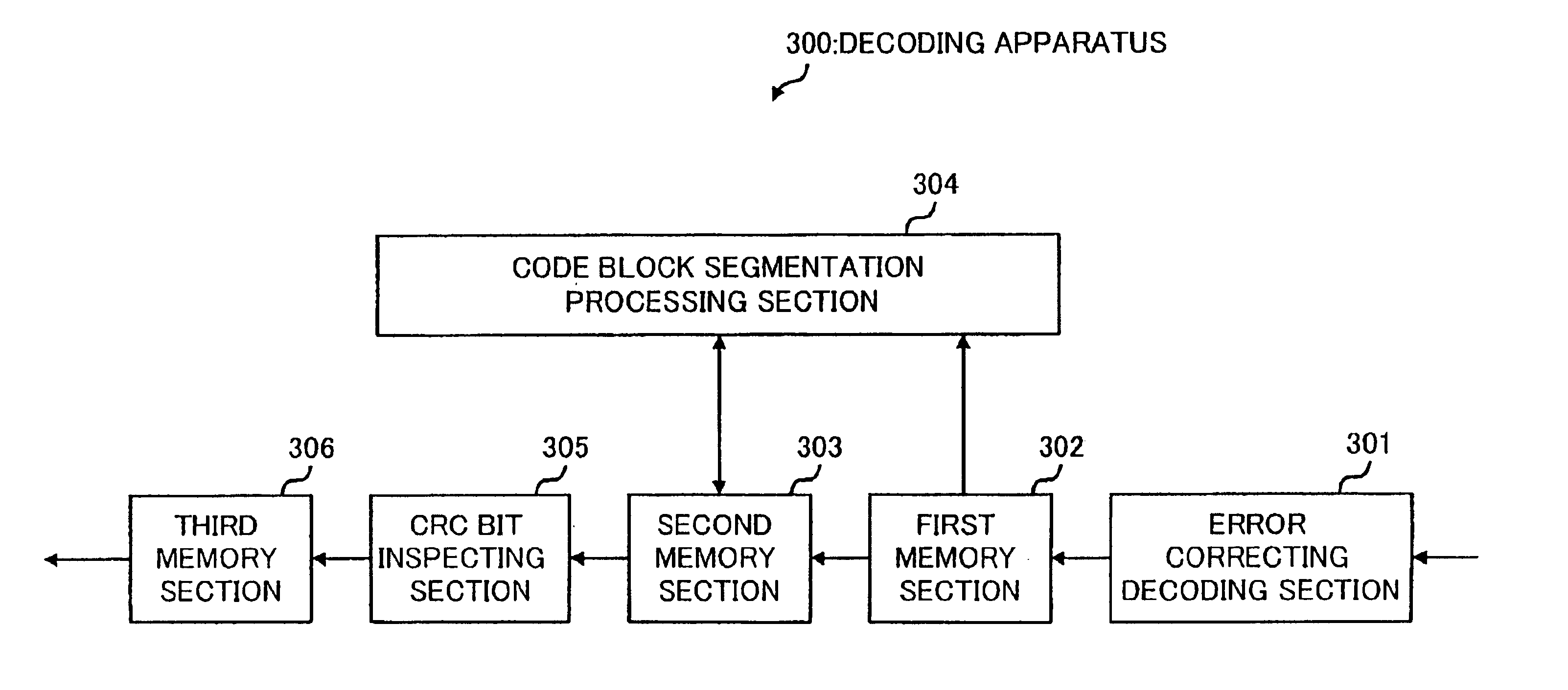
[0044]FIG. 3 is a block diagram showing a configuration of a decoding apparatus according to Embodiment 2 of the present invention.

[0045]The decoding apparatus 300 shown in FIG. 3 is used as a receiving means of a mobile station apparatus or base station apparatus, etc., and is provided with an error correcting decoding section 301, a first memory section 302, a second memory section 303, a code block segmentation processing section 304, a CRC bit inspecting section 305, and a third memory section 306.

[0046]Furthermore, as shown in FIG. 4, the code block segmentation processing section 304 is provided with a number of data detecting section 401, a data dividing / deleting position detecting section 402, and an access section 403.

[0047]In the above-described configuration, first, the error correcting decoding section 301 carries out error correcting decoding on the received signal that is encoded by error correcting coding processing at the coding apparatus 100 disc...


PUM


Abstract

A coding / decoding technique capable of increasing the error correcting decoding performance and improving the communication quality. This technique divides, through code block segmentation prior to error correcting coding, transmission data with CRC-bit added into a predetermined number of code blocks so that the data length of each code block is an integer multiple of the data length of each transport block and ensures that CRC-bit exists at the end of each code block. Then, the technique performs error correcting coding on each code block after the division.

Description

[0001]This application is a division of U.S. application Ser. No. 10 / 018,658, filed Dec. 21, 2001, which is a 371 of PCT / JP01 / 03380, filed Apr. 20, 2001.TECHNICAL FIELD[0002]The present invention relates to an apparatus and method for coding / decoding in a digital mobile communication system.BACKGROUND ART[0003]As one of error correcting coding / decoding processes in a third-generation mobile communication system, “code block segmentation” is proposed in the 3GPP technical standard document “TS 25.211 Ver3.1.0”.[0004]Code block segmentation is a means for uniformly dividing data and it is the means used to send large amount of data (in case of high bit rate) when the whole data to be sent is divided into a plurality of blocks and subjected to error correcting coding one-by-one instead of subjecting the whole data to be sent to an error correcting coding (e.g., convolutional coding or turbo coding, etc.). In addition, a unit just before division of data is called “transport block”, and...

Claims


Application Information

Patent Timeline
Patent Type & Authority Patents(United States)
IPC IPC(8): H03M13/09H03M13/00H03M13/29G06F11/10H03M13/15H03M13/45H04L1/00H04L25/02
CPCH03M13/09H03M13/091H03M13/29H04L1/0006H04L1/0045H04L1/0061H04L1/0065Y02E60/10A63H27/02A63H29/10A63H29/22A63H29/24H01M50/20
Inventor KAJITA, KUNIYUKI
Owner III HLDG 12 LLC
Features
  • R&D
  • Intellectual Property
  • Life Sciences
  • Materials
  • Tech Scout
  • Unparalleled Data Quality
  • Higher Quality Content
  • 60% Fewer Hallucinations
Learn More