Method for tensioning multiple-strand cables

a technology of tensioning and cable, applied in the direction of electrical digital data processing, structural/machine measurement, instruments, etc., can solve the problems of complex work, inconvenient adjustment of cable according to the specifications imposed by the design of the structure, and inability to meet the requirements of the structur

Inactive Publication Date: 2005-09-13
MARCHETTI MICHEL
View PDF4 Cites 24 Cited by
  • Summary
  • Abstract
  • Description
  • Claims
  • Application Information

AI Technical Summary

Benefits of technology

[0041]In a first embodiment: said expression which is a function of said predetermined parameter defines

Problems solved by technology

Moreover, although the prior art method imposes the same tension in all the strands at the time of installing the cable, the problem of adjusting a cable in accordance with the specifications imposed by the design of the structure remain outside the scope of the prior art method.
However, experience shows that this approach is imprecise, because of uncertainties as to the real load on the first strand, such as the real conditions of contact of the sheath, the pres

Method used


Image

  • Method for tensioning multiple-strand cables
  • Method for tensioning multiple-strand cables
  • Method for tensioning multiple-strand cables

Examples


first embodiment

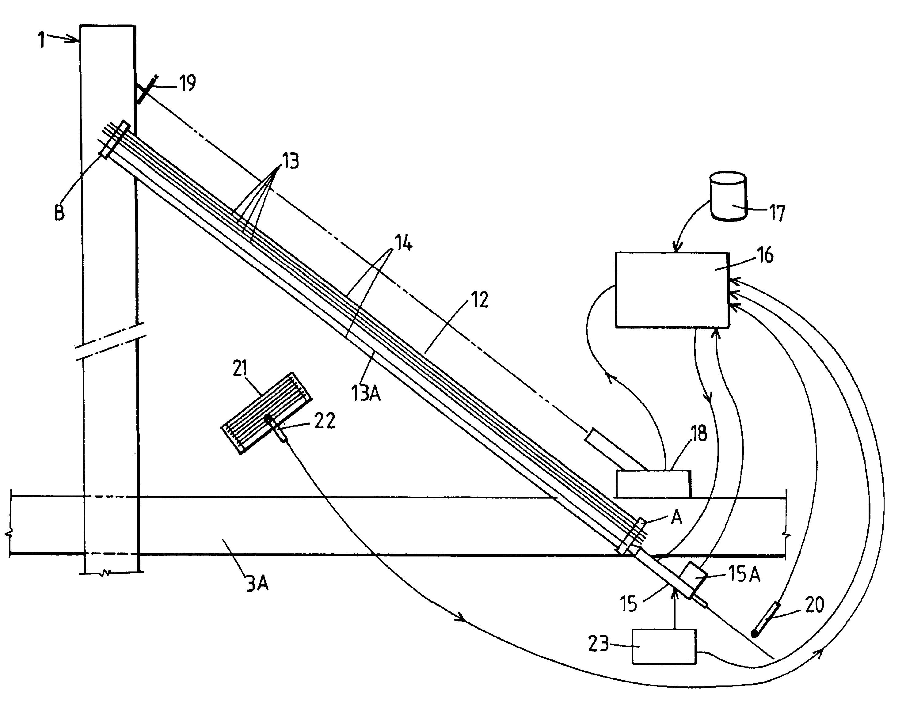
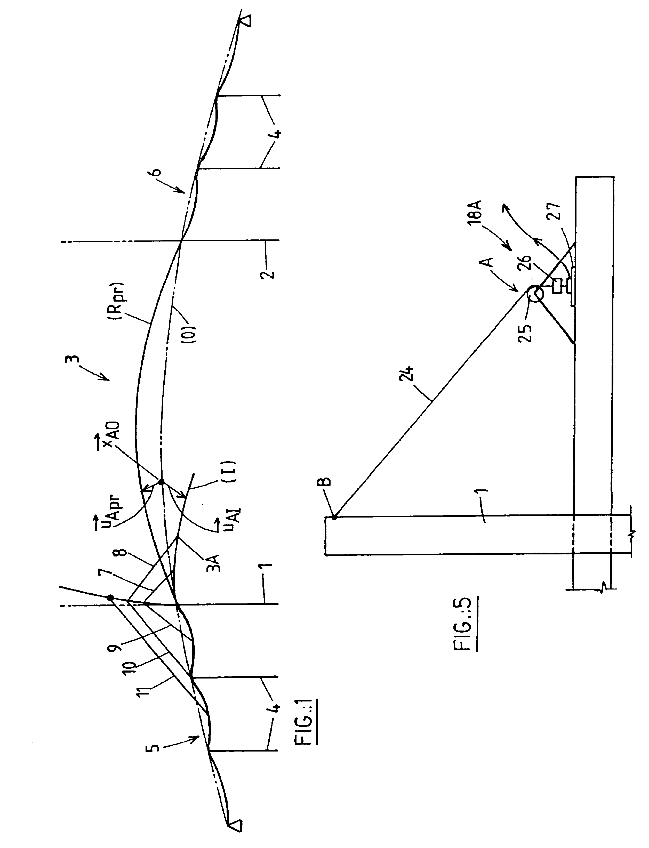
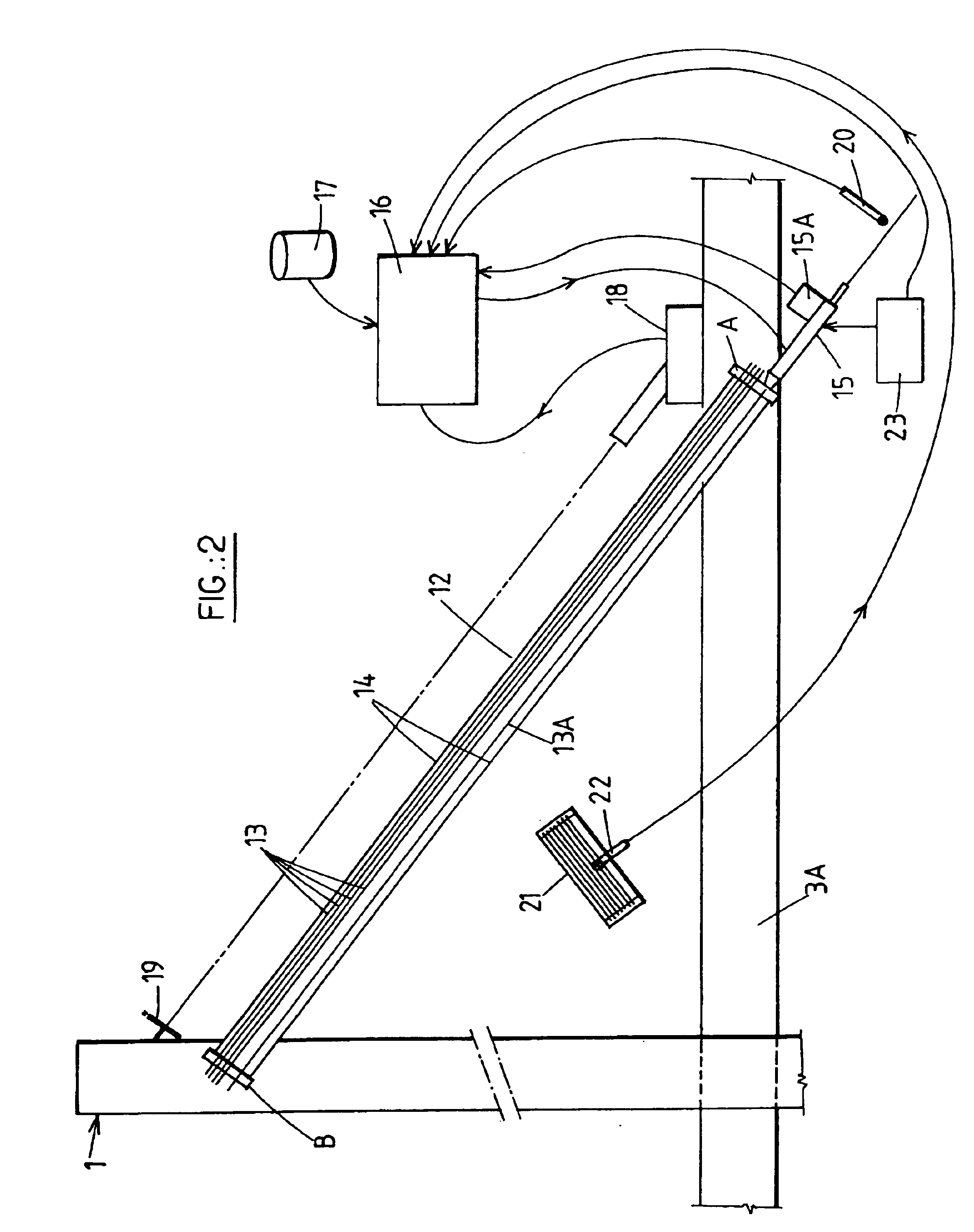
[0093]Referring from now on to FIG. 3, the computation algorithm used by the microcomputer 16 to execute a method according to the invention using data supplied to it by the tension sensor 15A, the permanent memory 17, the rangefinder 18 and the temperature sensor 20 is described. It is assumed that, using an appropriate topographical procedure, it has been possible to measure on site the effective values of the displacements {right arrow over (μ)}Ar and {right arrow over (μ)}Bt of the cable anchors, just before installing the first strand. If this is not the case, it is always possible to use theoretical values of these displacements taken into account in the design process for this phase, provided that the predicted loading is rigorously respected on site and these values are corrected by means of a computer, the corrections being necessary because the temperatures of the structure and the cables already installed generally differ from the theoretical values taken into account dur...

second embodiment

[0125]The second embodiment differs in the step S3, during which, instead of computing the stretch value Δl, a value T is computed representing the locking tension to be achieved in the strand 13A before anchoring can take place.

[0126]The locking tension Tbloc is determined from the values {right arrow over (AB)}, q* and Lθ using the following equation:

Tbloc=T(Ea,q*,{right arrow over (AB)},Lθ)

[0127]Note that the determination of the function T above can use the same elastic chain theory as described in the work previously cited, the problem to be solved being based on looking for the value T rather than the value of L.

[0128]The value of the locking tension Tbloc computed by the computer 16 is displayed in a window V2 of the screen and the real value of the tension in the strand 13A measured by means of the sensor 15A is displayed simultaneously in another window V1. Locking is effected as soon as the values in the windows V1 and V2 are equal. The process can be stopped automaticall...


PUM


Abstract

A method whereby the strands (13,13A) are fixed one after another between two cable anchors (A,B) integral with the structure. The method consists: in pulling on one of the ends of a strand (13A) from one (A) of the cable anchors, while the other end is fixed on the other cable anchor (B); continuously testing the tensioning condition of the strand (13A), the condition involving in particular the measured values of the strand tension and of a predetermined parameter. The invention is characterized in that the predetermined parameter is the variation of the distance separating the cable anchors (A,B).

Description

CROSS REFERENCE TO RELATED APPLICATION[0001]This is the 35 USC 371 national stage of International Application PCT / FR01 / 02775 filed on Sep. 6, 2001, which designated the United States of America.FIELD OF THE INVENTION[0002]The present invention relates to a method for tensioning multiple-strand cables.[0003]Multiple-strand cables can be used in all sorts of civil engineering structures, in particular to support structural members with a long span (bridge decks, stadium roofs) or to stabilize slender structures (for example microwave towers).[0004]Be this as it may, in these types of civil engineering structures, it is necessary to tension the strands of a cable so that:[0005]a) firstly, the total tension in a cable is uniformly distributed between all of the component strands, to prevent dangerous excess tensions in some strands, leading in particular to the risk of rupture by fatigue,[0006]b) secondly, the tension in the cable as a whole is adjusted to a value as close as possible ...

Claims


Application Information

Patent Timeline
IPC IPC(8): E01D19/16E04G21/12E01D19/00
CPCE01D19/16E04G21/12E04G21/121
Inventor MARCHETTI, MICHEL
Owner MARCHETTI MICHEL
Why Eureka
Try Eureka