Method of forming an optimized fiber reinforced liner on a rotor with a motor

a technology of fiber reinforced liner and rotor, which is applied in the direction of machines/engines, rotary piston liquid engines, and magnetic circuit shapes/forms/construction, etc., can solve the problems of increasing torque and drill bit rpm, swelling and thermal fatigue, and failure of pdm

Inactive Publication Date: 2005-09-20
SCHLUMBERGER TECH CORP
View PDF26 Cites 34 Cited by
  • Summary
  • Abstract
  • Description
  • Claims
  • Application Information

AI Technical Summary

Problems solved by technology

However, directional drilling may also be performed by rotating the drill string and using the PDM, thereby increasing the available torque and drill bit rpm.
This process, which may be referred to as “chunking,” deteriorates the seal formed between the rotor 10 and stator 20 and may cause failure of the PDM.
Swelling and thermal fatigue may be caused by elevated temperatures and exposure to certain drilling fluids and formation fl

Method used


Image

  • Method of forming an optimized fiber reinforced liner on a rotor with a motor
  • Method of forming an optimized fiber reinforced liner on a rotor with a motor
  • Method of forming an optimized fiber reinforced liner on a rotor with a motor

Examples


Embodiment Construction

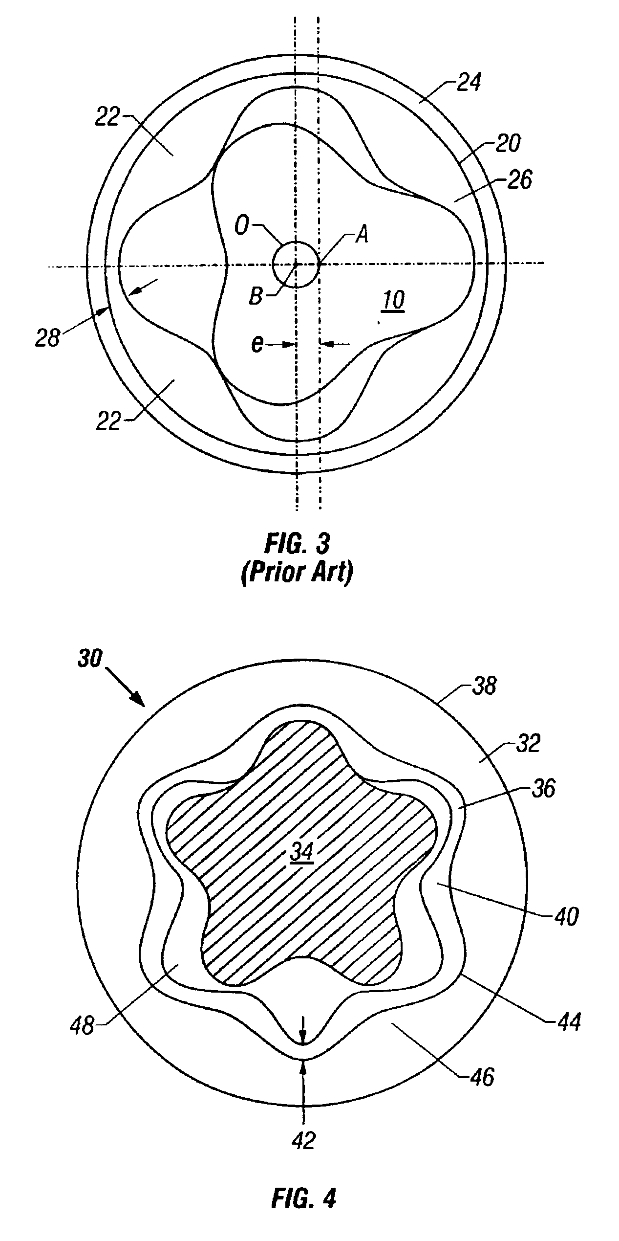
[0033]FIG. 4 shows an embodiment comprising at least one aspect of the present invention. A positive displacement motor (PDM) 30 comprises a stator 32 and a rotor 34. The stator 32 comprises an external tube 38 that may be formed from, for example, steel or another material suitable for downhole use in a drilling environment. The stator also comprises a liner 36.

[0034]The external tube 38 comprises a shaped inner surface 44 that comprises at least two lobes 46 formed thereon. The lobes 46 are helically formed along a selected length of the external tube 38 so that the lobes 46 define a helical pattern along the selected length. The helical form of the inner surface 44 generally corresponds to a desired shape for stator lobes. The liner 36 typically comprises at least two lobes 40, and a thickness 42 of the liner 36 may be either uniform or non-uniform throughout a cross-section thereof. Accordingly, the embodiments shown herein comprising a non-uniform cross-section are intended to ...


PUM

PropertyMeasurementUnit
Temperatureaaaaaaaaaa
Lengthaaaaaaaaaa
Angleaaaaaaaaaa

Abstract

A method of forming a rotor for a positive displacement motor. The method includes forming a liner that includes at least two resilient layers and at least one fiber layer, and the at least two resilient layers are positioned so as to enclose the at least one fiber layer. The liner is positioned on a rotor tube, and the rotor tube includes a shaped outer surface including at least two radially outwardly projecting lobes extending helically along a selected length of the rotor tube. The liner is cured on the rotor tube so that the liner conforms to the radially outwardly projecting lobes formed on the outer surface and to the helical shape of the outer surface. The curing forms a bond between the liner and the outer surface and between the at least two resilient layers and the at least one fiber layer.

Description

CROSS REFERENCE TO RELATED APPLICATIONS[0001]This is a divisional of U.S. patent application Ser. No. 10 / 097,480 filed Mar. 14, 2002, now U.S. Pat. No. 6,604,922.BACKGROUND OF INVENTION[0002]1. Field of the Invention[0003]The invention relates generally to stators used with positive displacement drilling motors. More specifically, the invention relates to a fiber reinforced liner adapted for use with formed stators.[0004]2. Background Art[0005]Positive Displacement Motors (PDMs) are known in the art and are commonly used to drill wells in earth formations. PDMs operate according to a reverse mechanical application of the Moineau principle wherein pressurized fluid is forced though a series of channels formed on a rotor and a stator. The channels are generally helical in shape and may extend the entire length of the rotor and stator. The passage of the pressurized fluid generally causes the rotor to rotate within the stator. For example, a substantially continuous seal may be formed ...

Claims


Application Information

Patent Timeline
IPC IPC(8): B29C70/04B29C70/08B29C70/34F04C2/00F04C2/107B29C53/00B29C63/06B29C53/38B29C63/02
CPCB29C70/086B29C70/342F04C2/1075B29C53/38Y10T29/49009B29K2021/00B29K2105/0845B29K2277/10B29K2307/00B29K2309/08B29L2009/00B29L2031/749F04C2230/27F05C2253/04F05C2253/16Y10T29/49236Y10T29/49012Y10T29/53143B29C63/06
Inventor HACHE, JEAN-MICHEL
Owner SCHLUMBERGER TECH CORP
Why Eureka
Try Eureka