
Surgical stapling apparatus

a technology of surgical stapling and stapler, which is applied in the direction of surgical staples, surgical forceps, paper/cardboard containers, etc., can solve the problems of increasing the time, complexity and overall cost of laparoscopic surgical procedures, and the cost of designing and manufacturing multiple stapler sizes, rather than creating, and increasing the cost of time and complexity

Inactive Publication Date: 2005-10-11
UNITED STATES SURGICAL CORP
View PDF106 Cites 2389 Cited by
  • Summary
  • Abstract
  • Description
  • Claims
  • Application Information

AI Technical Summary

Benefits of technology

"The present disclosure describes a surgical stapling apparatus that can apply multiple fasteners to body tissue and simultaneously incise tissue. The apparatus can use disposable loading units with rows of staples and can be adapted to use articulating or non-articulating units. The apparatus includes a handle assembly with a movable handle and a stationary handle, an elongated body, and an actuation shaft with a toothed rack and a control rod. The apparatus also has an articulation mechanism with an articulation lever and a cam member, and a sensing mechanism to detect the type of disposable loading unit. The technical effects of this invention include improved efficiency and precision in surgical procedures and reduced trauma to the patient."

Problems solved by technology

Such practices increase the time, complexity and overall costs associated with laparoscopic surgical procedures.
In addition, costs are greater in designing and manufacturing multiple stapler sizes, as opposed to creating a single, multipurpose stapler.

Method used


Image

  • Surgical stapling apparatus
  • Surgical stapling apparatus
  • Surgical stapling apparatus

Examples


Embodiment Construction

[0087]Preferred embodiments of the presently disclosed endoscopic surgical stapling apparatus will now be described in detail with reference to the drawings, in which like reference numerals designate identical or corresponding elements in each of the several views.

[0088]In the drawings and in the description that follows, the term “proximal”, as is traditional, will refer to the end of the stapling apparatus which is closest to the operator, while the term distal will refer to the end of the apparatus which is furthest from the operator.

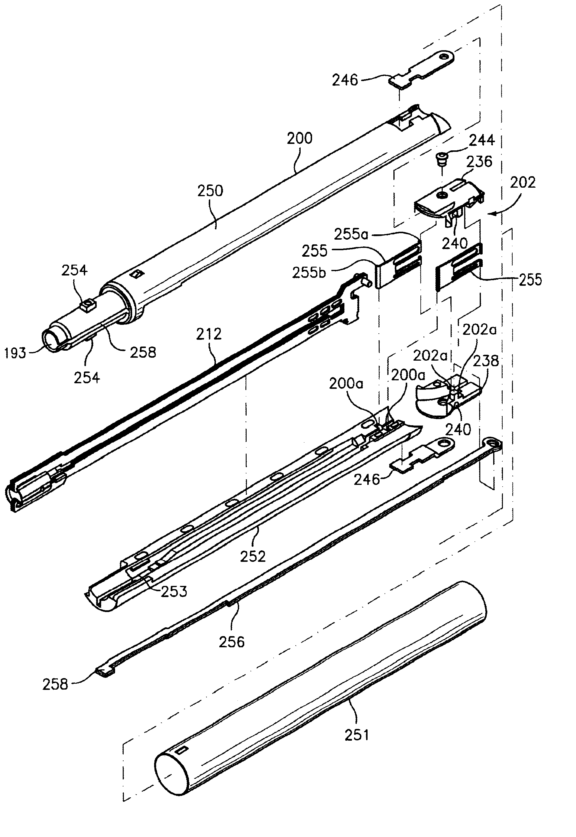
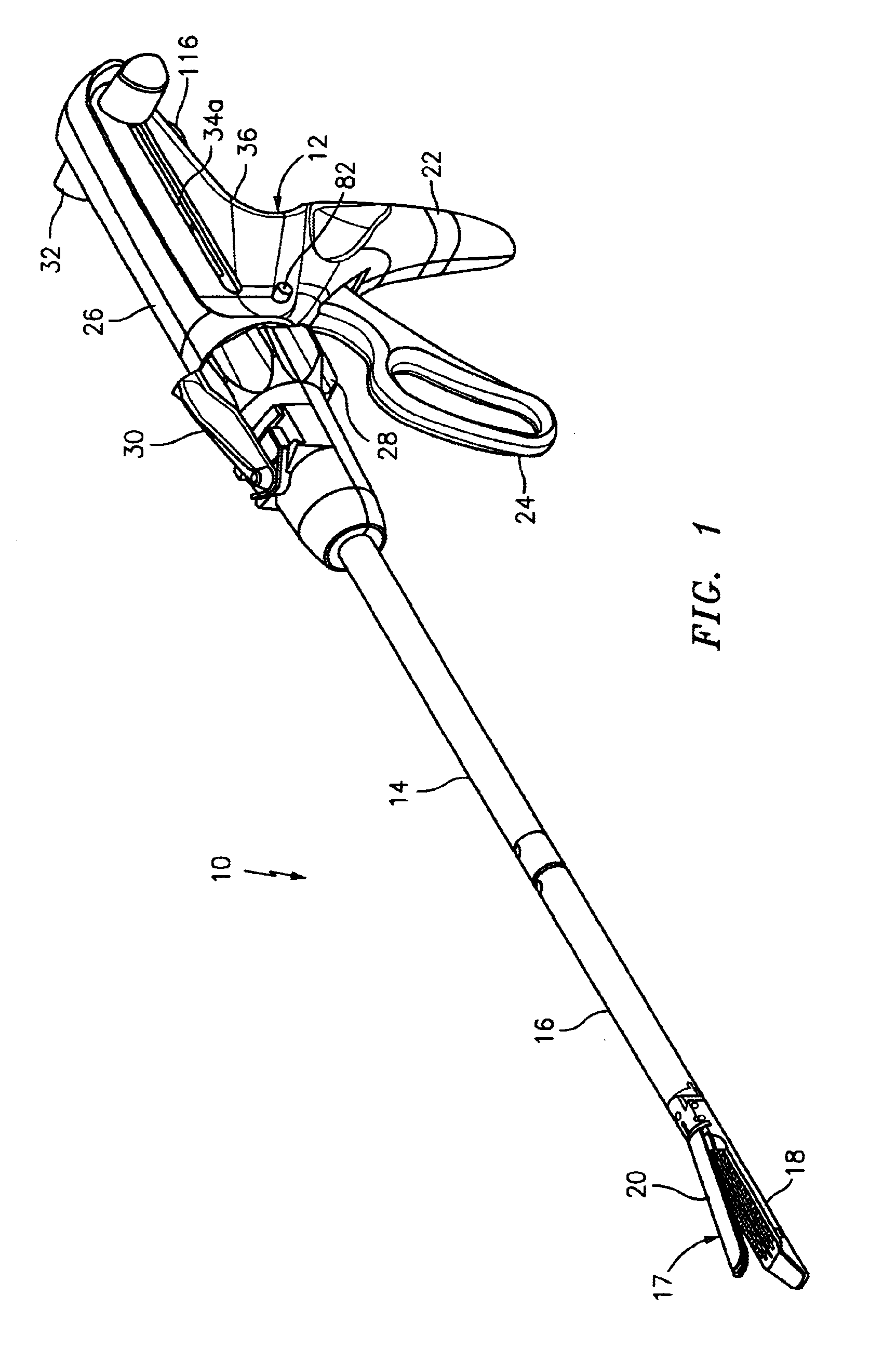
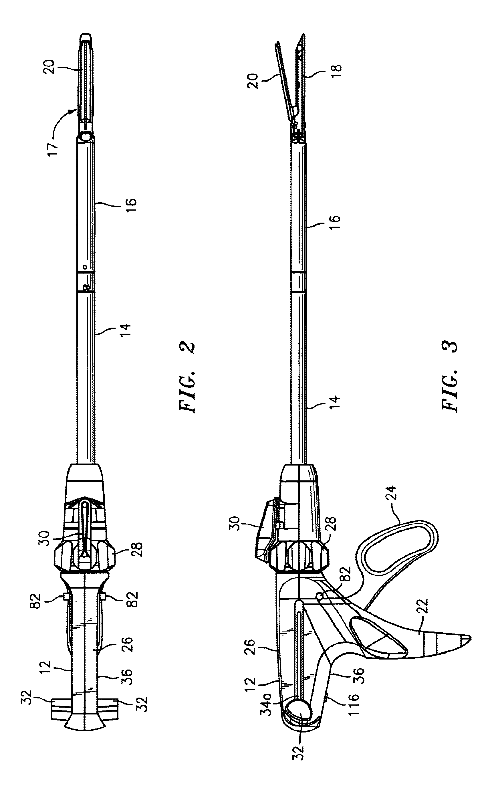
[0089]FIGS. 1-3 illustrate one embodiment of the presently disclosed surgical stapling apparatus shown generally as 10. Briefly, surgical stapling apparatus 10 includes a handle assembly 12 and an elongated body 14. A disposable loading unit or DLU 16 is releasably secured to a distal end of elongated body 14. Disposable loading unit 16 includes a tool assembly 17 having a cartridge assembly 18 housing a plurality of surgical staples and an anvil as...


PUM

PropertyMeasurementUnit
lengthaaaaaaaaaa
lengthaaaaaaaaaa
lengthaaaaaaaaaa

Abstract

A surgical stapling device particularly suited for endoscopic procedures is described. The device includes a handle assembly and an elongated body extending distally from the handle assembly. The distal end of the elongated body is adapted to engage a disposable loading unit. A control rod having a proximal end operatively connected to the handle assembly includes a distal end extending through the elongated body. A control rod locking member is provided to prevent movement of the control rod until the disposable loading unit is fully secured to the elongated body of the stapling device.

Description

CROSS-REFERENCE TO RELATED APPLICATIONS[0001]This application is a continuation of U.S. patent application Ser. No. 10 / 700,250 filed Nov. 3, 2003 ABN, which is a continuation of U.S. patent application Ser. No. 10 / 014,004, filed Dec. 10, 2001 U.S. Pat. No. 6,669,073, which is a continuation of U.S. patent application Ser. No. 09 / 680,093, filed Oct. 5, 2000 U.S. Pat. No. 6,330,965, which is a divisional of U.S. patent application Ser. No. 09 / 561,567, filed Apr. 28, 2000 U.S. Pat. No. 6,241,139, which is a divisional of U.S. patent application Ser. No. 09 / 166,378, filed Oct. 5, 1998 U.S. Pat. No. 6,079,606, which is a divisional of U.S. patent application Ser. No. 08 / 935,980, filed Sep. 23, 1997, now U.S. Pat. No. 5,865,361, all of which are incorporated herein in their entirety by reference.BACKGROUND[0002]1. Technical Field[0003]This application relates to a surgical stapling apparatus, and more particularly, to an articulating mechanism for use with an endoscopic surgical stapling ...

Claims


Application Information

Patent Timeline
Patent Type & Authority Patents(United States)
IPC IPC(8): A61B17/068A61B17/04A61B17/00A61B17/072A61B17/28
CPCA61B17/07207A61B17/072A61B17/068A61B2017/0023A61B2017/00473A61B2017/00477A61B2017/07214A61B2017/2923A61B2017/2927A61B2017/2929A61B2017/2946A61B2017/07278A61B17/0686A61B17/105A61B17/115A61B2090/0806A61B2090/0808
Inventor MILLIMAN, KEITH L.VIOLA, FRANK J.ORBAN III, JOSEPHLEHN, RANDOLPH F.
Owner UNITED STATES SURGICAL CORP
Learn More