Methods for designing composite ophthalmic lens surfaces

a technology of composite ophthalmic lenses and lenses, applied in the field of ophthalmic lenses, can solve the problem that the composite surface does not have the desired surface power profil

Active Publication Date: 2005-10-18
ESSILOR INT CIE GEN DOPTIQUE
View PDF6 Cites 105 Cited by
  • Summary
  • Abstract
  • Description
  • Claims
  • Application Information

AI Technical Summary

Problems solved by technology

However, using this method is disadvantageous in that the resulting composite surface will not have the desired surface power profile in the cases in which the base curves of the two surfaces being combined are different.

Method used


Image

  • Methods for designing composite ophthalmic lens surfaces
  • Methods for designing composite ophthalmic lens surfaces
  • Methods for designing composite ophthalmic lens surfaces

Examples


example

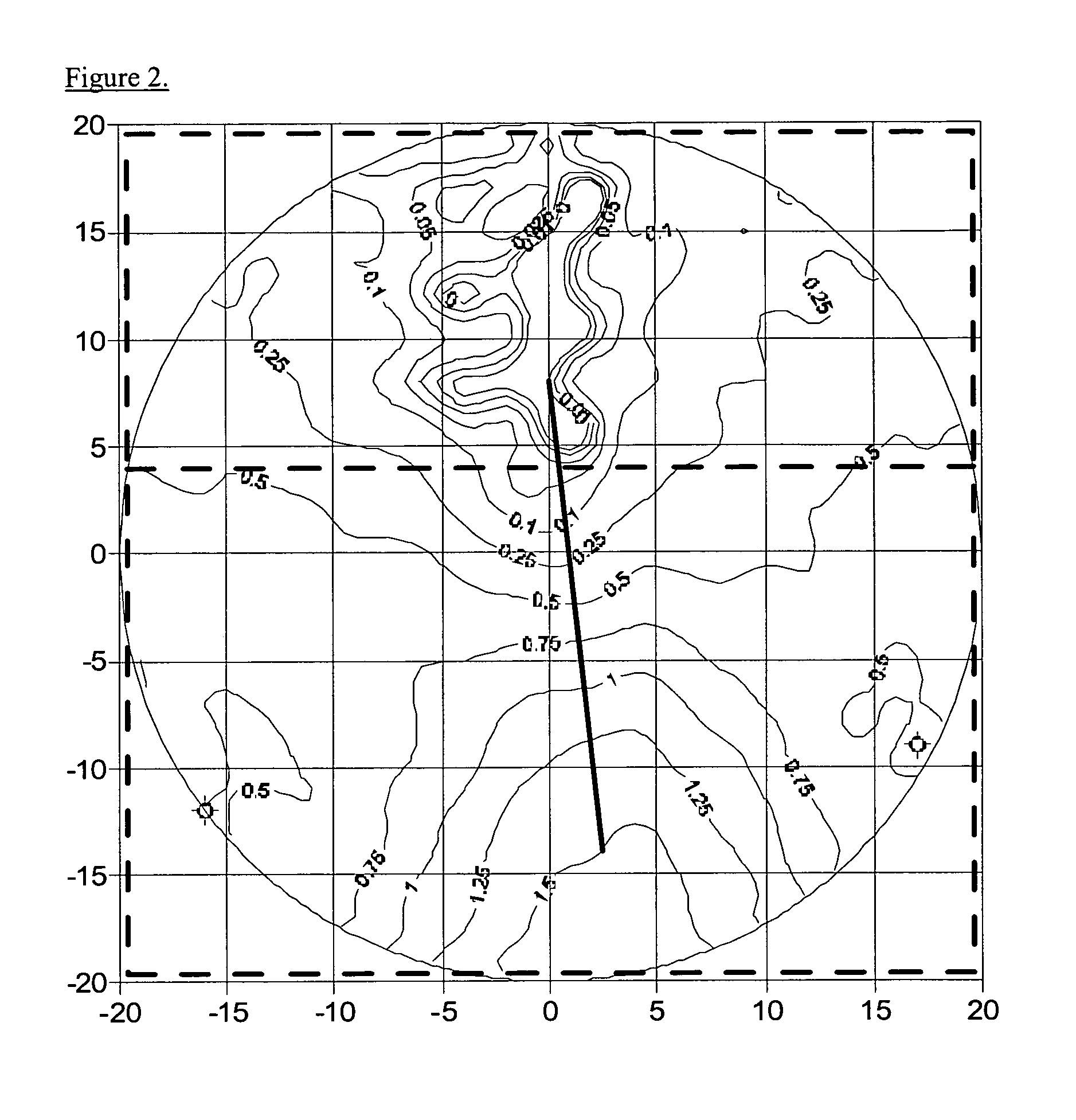
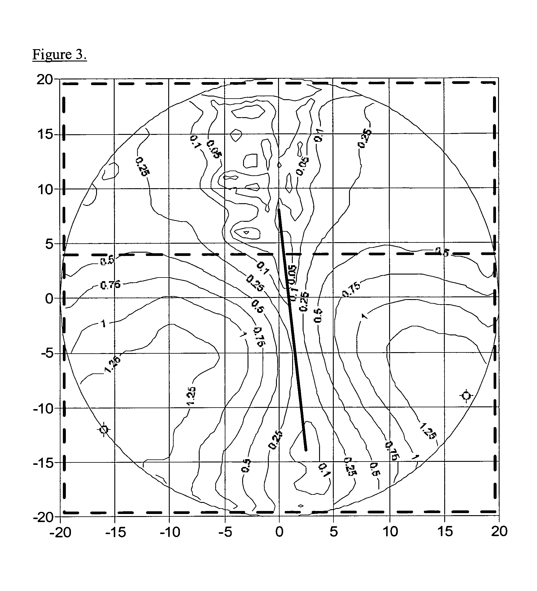
[0047]A Varilux COMFORT™ lens with a 2.0 diopters base power and a 1.5 diopters add power was measured using a coordinate measuring machine. The power and unwanted cylinder profiles are shown as FIGS. 2 and 3. A Varilux PANAMIC™ lens with a 5.5 diopters base power and a 1.5 diopters add power was measured and the power and unwanted cylinder profiles are shown in FIGS. 4 and 5.

[0048]A composite surface was to be created with a base power of 6.0 diopters and a target add power of 3.0 diopters. The surface was first created by sag addition of the measured COMFORT and PANAMIC surfaces. The surface had an add power of 2.89 diopters. The power and unwanted cylinder profiles for this surface are shown as FIGS. 6 and 7, respectively. The surface was then created using the curvature addition method of the invention. The resulting lens had an add power of 3.0 diopters. The power and unwanted cylinder profiles for this surface are shown as FIGS. 8 and 9.


PUM


Abstract

The invention provides a method for designing a composite lens surface by using vector addition of the surface curvatures of two or more lens surfaces and then constructing a surface by numerical integration.

Description

FIELD OF THE INVENTION[0001]The present invention relates to ophthalmic lenses. In particular, the invention provides lens designs and lenses in which at least one surface of the lens is a composite of two or more surfaces.BACKGROUND OF THE INVENTION[0002]The use of ophthalmic lenses for the correction of ametropia is well known. For example, multifocal lenses, such as progressive addition lenses (“PALs”), are used for the treatment of presbyopia. The progressive surface of a PAL provides far, intermediate, and near vision in a gradual, continuous progression of vertically increasing dioptric power from far to near focus, or top to bottom of the lens.[0003]Ophthalmic lens surfaces may be designed using any of a wide variety of known methods. In one such method, a progressive surface is designed by combining two progressive surfaces. More specifically, a composite surface design is computed by adding the difference in sag value between a progressive surface and a base spherical surfa...

Claims


Application Information

Patent Timeline
Patent Type & Authority Patents(United States)
IPC IPC(8): G02C7/02
CPCG02C7/024G02C7/028G02C7/041G02C7/061
Inventor WOOLEY, C. BENJAMINGERLIGAND, PIERRE-YVES
Owner ESSILOR INT CIE GEN DOPTIQUE
Why Eureka
Try Eureka