
Clutch apparatus with automatic centrifugal engagement of pressure plate

a technology of centrifugal engagement and pressure plate, which is applied in the direction of mechanical actuators, clutches, and clutches, can solve the problems of difficult adjustment of new riders to smoothly engage the clutch, difficult control of the clutch engagement and application, and difficulty in adjusting the clutch lever

Inactive Publication Date: 2005-10-25
REKLUSE RACING LLC
View PDF7 Cites 24 Cited by
  • Summary
  • Abstract
  • Description
  • Claims
  • Application Information

AI Technical Summary

Benefits of technology

[0012]It is another object of the invention to optionally provide a manual override to disengage the clutch via a driver operated handlebar lev

Problems solved by technology

Although the lever operated clutch allows the driver to control the clutch engagement / disengagement, often times motorcycle drivers find the clutch lever difficult to operate smoothly.
New riders have difficulty adjusting to smoothly engaging the clutch while operating the throttle to move the vehicle from a standing start.
Motorcycle racers often have a difficult time controlling the engagement of the clutch and the application of the throttle to maximize acceleration.
Off-road motorcycle racers often need to stop the rear wheel suddenly with the rear brake, causing the engine to stall if the clutch is not first disengaged.
Clutch lever override not possible at high engine speeds.
At higher engine speeds, the increased centrifugal force of the engagement mechanism becomes difficult or impossible to overcome.
Too much centrifugal force at high engine speeds.
The excessive force traveling through the clutch may cause a failure in the engine or transmission.
Difficult to adjust automatic clutch.
Removal of the engine cover to adjust the clutch during riding is difficult for the rider.
Other automatic clutch solutions exist but all of the prior art fails to address all of the needs described.

Method used


Image

  • Clutch apparatus with automatic centrifugal engagement of pressure plate
  • Clutch apparatus with automatic centrifugal engagement of pressure plate
  • Clutch apparatus with automatic centrifugal engagement of pressure plate

Examples


Embodiment Construction

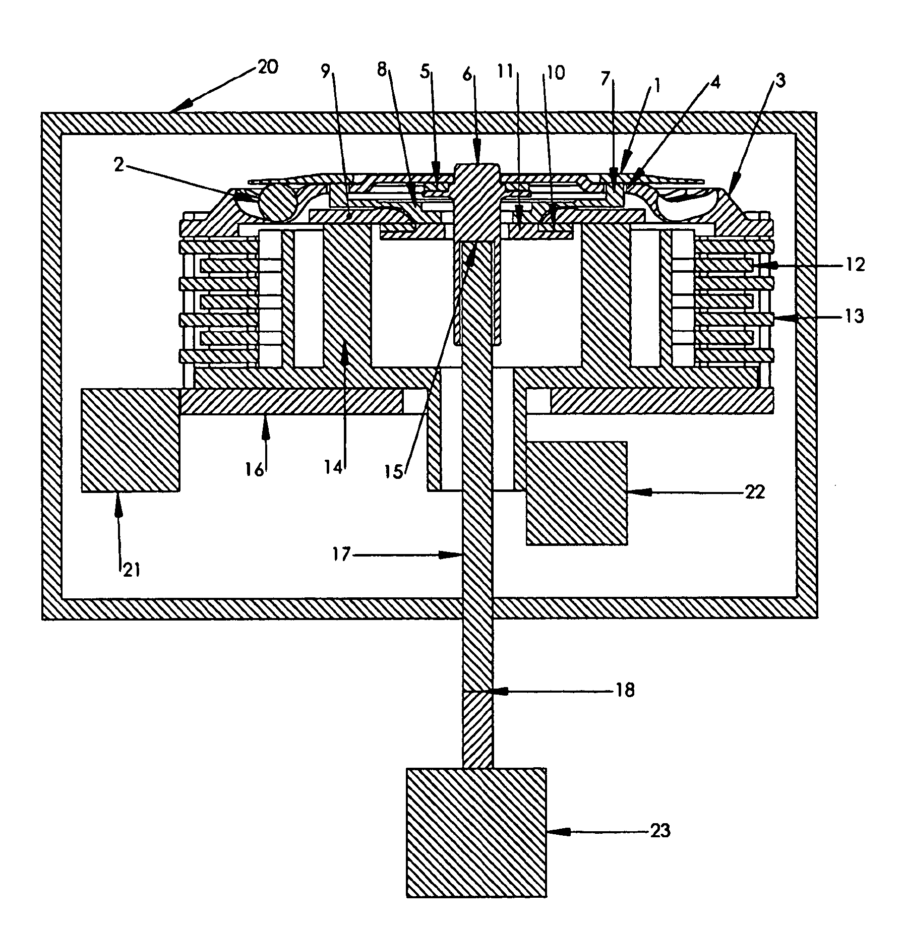
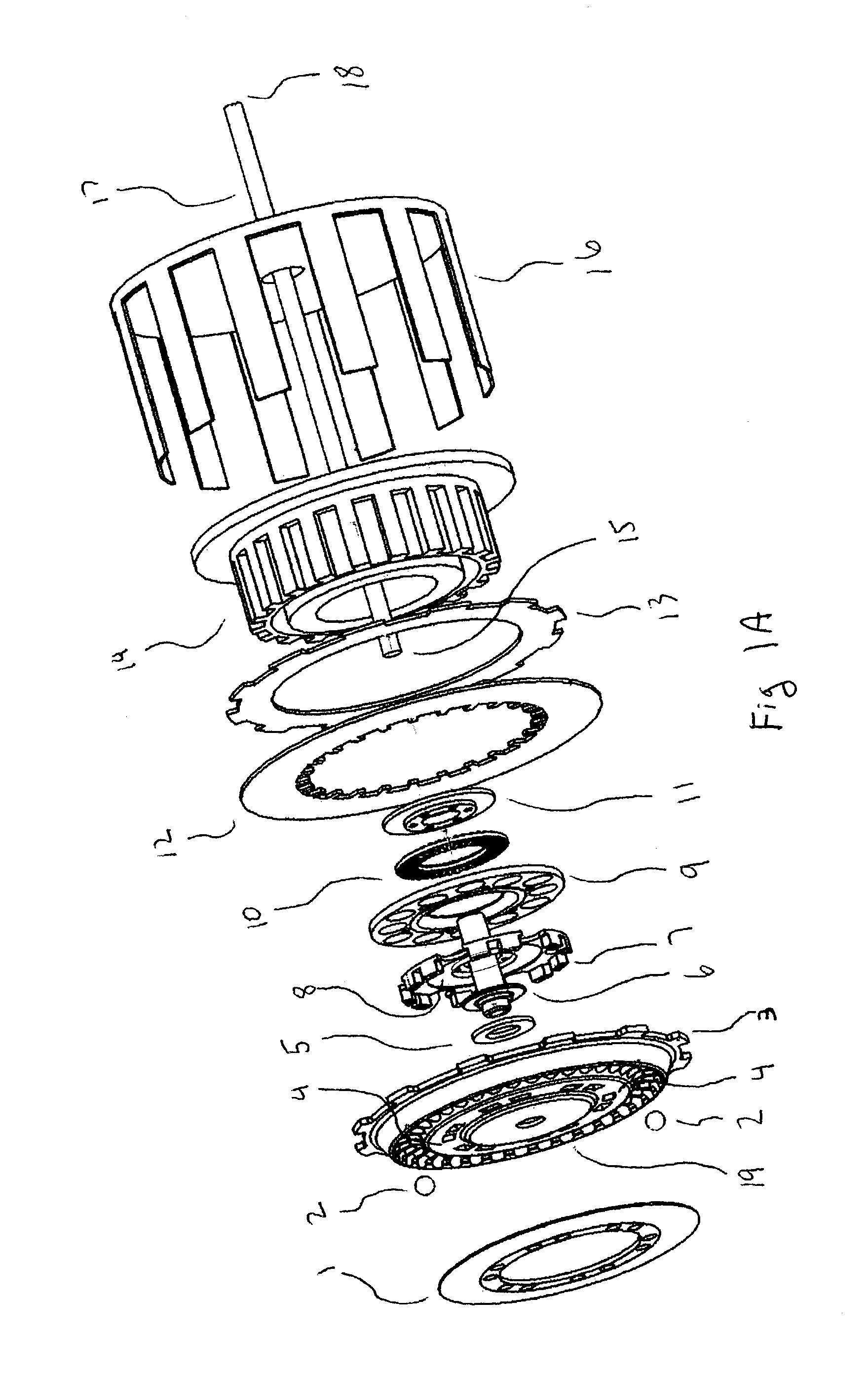
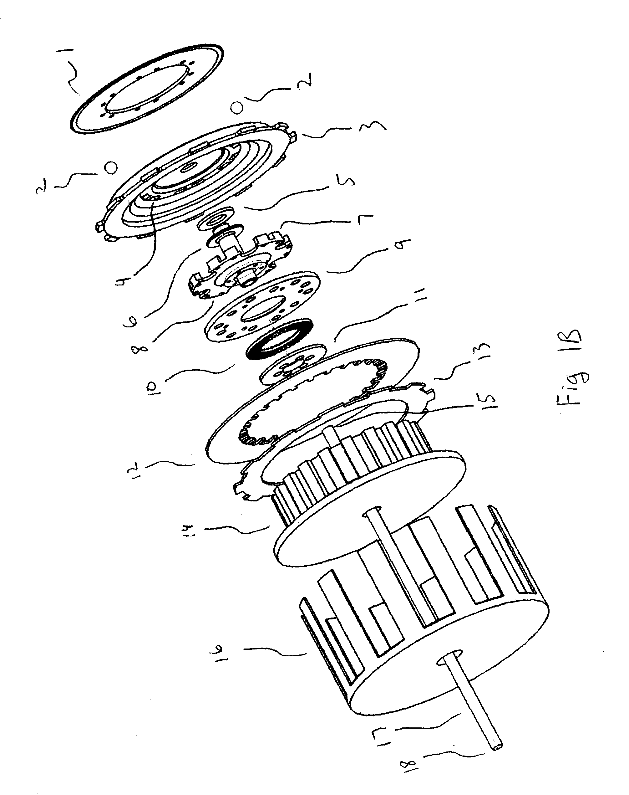
[0043]A preferred embodiment of the present invention is illustrated in FIG. 1A (rearward, exploded isometric view), FIG. 1B (forward, exploded isometric view) and FIG. 2 (cross-sectional view). The Upper Thrust (9) is sandwiched between the Rotating Hub (8), Thrust Bearing (10) and Lower Thrust (11). The Lower Thrust (11) is fixed to the bottom of the Rotating Hub (8). The Upper Thrust (9) is attached to the Clutch Inner Hub (14). The Pressure Plate (3) is sandwiched between the Top Plate (1) and the Rotating Hub (8). The Holes (4) of the Pressure Plate (3) pass over the Stand-Offs (7) of the Rotating Hub (8). The Ball(s) (2) are sandwiched between the Pressure Plate (3) and the Top Plate (1). The Lifter Thrust Bearing (5) sits on top of the Lifter (6). The Lifter Thrust Bearing (5) and Lifter (6) are sandwiched between the Pressure Plate (3) and the Rotating Hub (8). The Driven Friction Plate(s) (12) are coupled rotationally to the Clutch Inner Hub (14). The Driving Friction Plate...


PUM


Abstract

An automatic clutch consisting of a centrifugally actuated pressure plate apparatus axially moveable relative to a clutch inner hub and rotationally coupled to a clutch outer basket. As the engine spins the clutch outer basket, the rotational coupling between the clutch outer basket and the centrifugal pressure plate causes the centrifugal pressure plate to move axially relative to the clutch inner hub and apply a force to driven clutch plates and driving clutch plates. The force exerted by the centrifugal pressure plate upon driven clutch plates and driving clutch plates causes the plates to couple, forcing engagement between the engine and transmission. Optionally, a variable spring tension may be applied through the clutch release mechanism to adjust the engine speed at which the clutch begins to engage.

Description

CROSS-REFERENCE TO RELATED APPLICATIONS[0001]This application is based upon provisional application 60 / 384,910 filed on Jun. 3, 2002.FEDERALLY SPONSORED RESEARCH[0002]Not applicable.BACKGROUND OF THE INVENTION[0003]This invention pertains to the field of clutch engaging / disengaging mechanisms. More particularly, it is a device for automatically engaging or disengaging the clutch based upon engine speed.[0004]Most motorcycles incorporate a manual transmission coupled to the engine via a multi-plate clutch assembly. Typically, the multi-plate clutch is engaged / disengaged by the driver via a lever mounted on the handlebar. Although the lever operated clutch allows the driver to control the clutch engagement / disengagement, often times motorcycle drivers find the clutch lever difficult to operate smoothly. New riders have difficulty adjusting to smoothly engaging the clutch while operating the throttle to move the vehicle from a standing start. Experienced riders may need to partially di...

Claims


Application Information

Patent Timeline
IPC IPC(8): F16D43/12F16D43/00F16D43/10
CPCF16D43/10
Inventor YOUNGWERTH, ALBERT J.
Owner REKLUSE RACING LLC
Learn More