Double-row angular contact ball bearing

Active Publication Date: 2005-10-25
SCHAEFFLER TECH AG & CO KG
View PDF9 Cites 30 Cited by
  • Summary
  • Abstract
  • Description
  • Claims
  • Application Information

AI Technical Summary

Benefits of technology

[0004]It is an object of the invention to provide an improved rolling b

Problems solved by technology

A drawback of this bearing is that when the outer ring is not in place,

Method used


Image

  • Double-row angular contact ball bearing
  • Double-row angular contact ball bearing
  • Double-row angular contact ball bearing

Examples


Example

DETAILED DESCRIPTION OF THE DRAWINGS

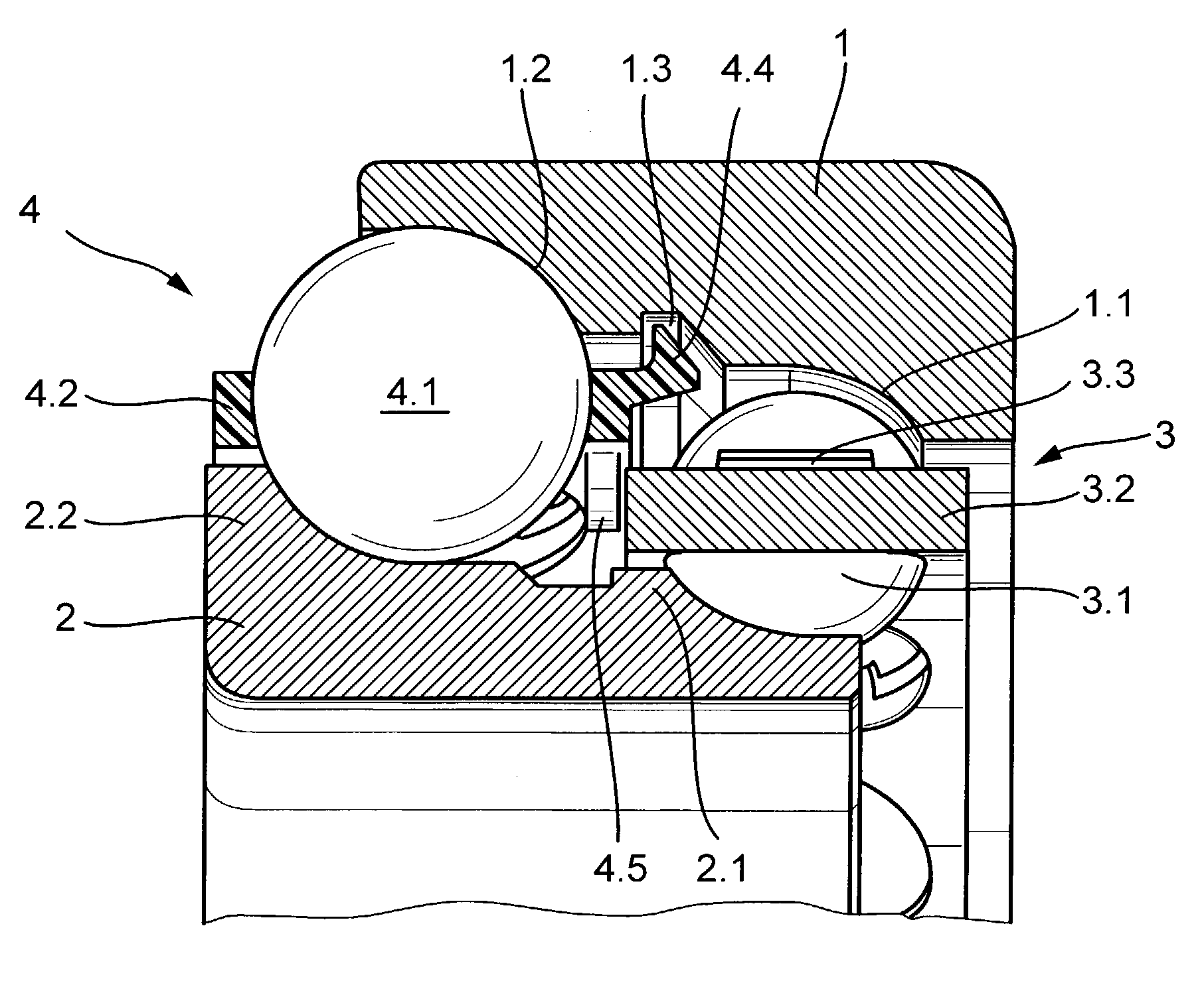
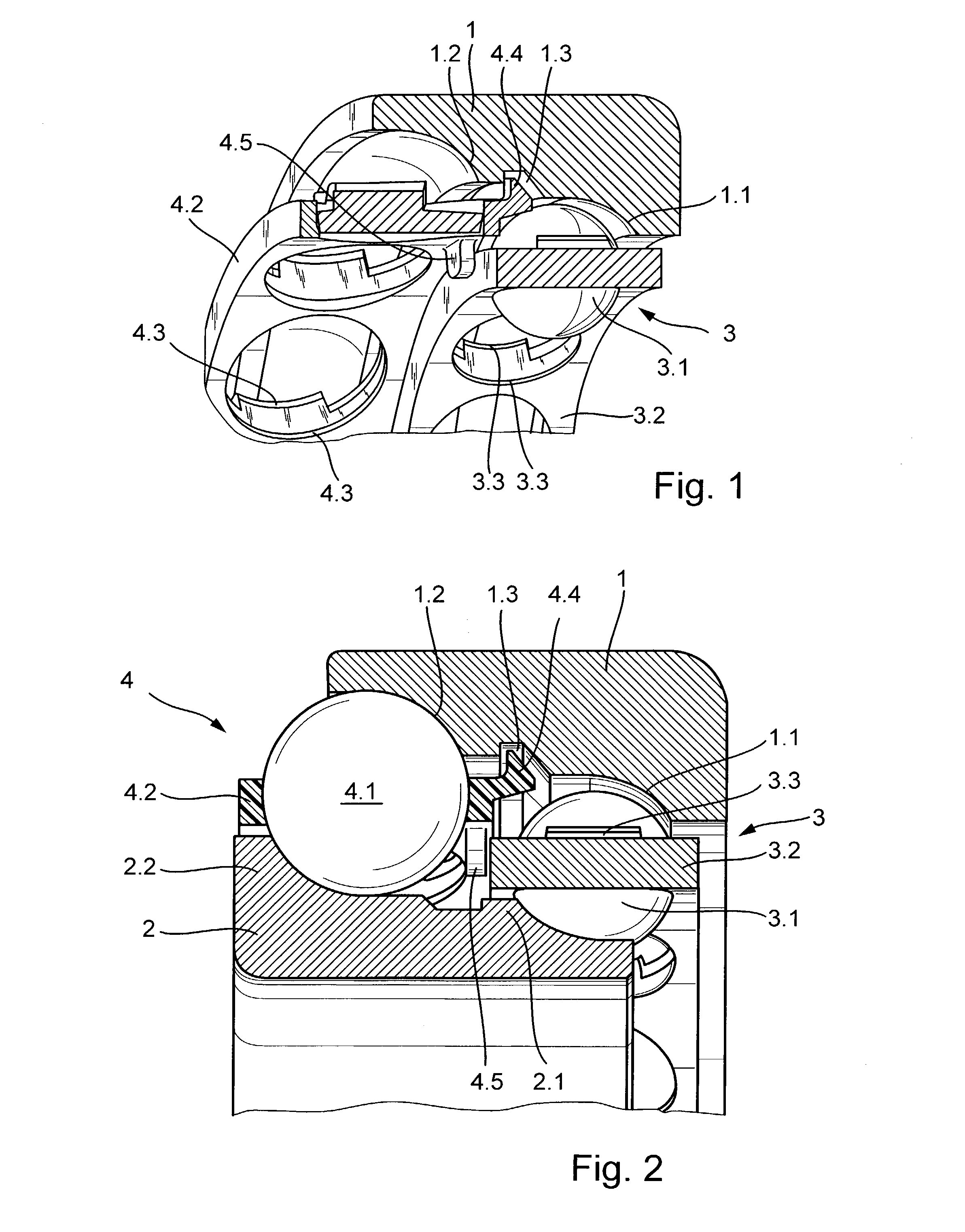
[0023]The bearing arrangement shown in FIGS. 1 and 2 comprises an outer ring 1 and an inner ring 2 between which ball crown rings 3, 4 made up of bearing balls 3.1, 4.1 and cages 3.2, 4.2 are arranged on associated raceways. Both cages 3.2, 4.2 comprise retaining elements 3.3, 4.3 that prevent an escape of the bearing balls 3.1, 4.1 in radially outward and radially inward direction from their respective cages 3.2, 4.2. Both bearing rings 1, 2 comprise shoulders 1.1, 1.2, 2.1, 2.2 against which the bearing balls 3.1, 4.1 bear. These figures also show that the two ball crown rings 3, 4 have different pitch circle radii and the ball raceways likewise have different diameters.

[0024]As can be seen further in FIGS. 1 and 2, the cage 4.2 of the invention is configured on its end oriented toward the interior of the bearing with a plurality of retaining lugs 4.4 that are uniformly spaced in peripheral direction and engage an associated groove 1.3 of the ou...


PUM


Abstract

In a double-row angular contact ball bearing comprising an outer ring (1), an inner ring (2) and two ball crown rings (3, 4) formed by bearing balls (3.1, 4.1) guided in two separate cages (3.2, 4.2) and supported on shoulders (1.1, 1.2, 2.1, 2.2) of said inner and outer rings, ball raceways of the bearing having different diameters, the cages (3.2, 4.2) are made of plastic and configured as window-type cages comprising pockets for receiving the bearing balls (3.1, 4.1), and one of the cages (3.2, 4.2) comprises on an axially inward oriented end, a plurality of spacers (3.5, 4.5) uniformly spaced from one another in peripheral direction, said one cage further comprises a plurality of retaining lugs (3.4, 4.4) uniformly spaced from one another in peripheral direction, which retaining lugs engage a corresponding groove (2.3, 1.3) of one of the inner (2) and the outer ring (1), and the spacers (3.5, 4.5) of the one cage (3.2, 4.2) prevent an axial displacement of the other cage (4.2, 3.2).

Description

FIELD OF THE INVENTION[0001]The invention concerns a double-row angular contact ball bearing comprising an outer ring, an inner ring and cage-guided bearing balls supported on shoulders of said inner and outer rings, ball raceways of the bearing having different diameters.BACKGROUND OF THE INVENTION[0002]A double-row angular contact ball bearing of the pre-cited type is known from WO85 / 03749. The bearing shown in FIG. 2 of this earlier publication comprises an inner ring and an outer ring both of which have shoulders on which the ball rows are supported when a force is applied. Each of the ball rows is accommodated in a separate cage.[0003]A drawback of this bearing is that when the outer ring is not in place, both the ball crown rings can slip off the inner ring in axial direction. But assembly conditions are conceivable in which, at first, one of the bearing rings has to be fixed on a shaft or in a housing while, at the same time, a retention of the rolling elements on this bearin...

Claims


Application Information

Patent Timeline
IPC IPC(8): F16C33/38F16C19/02F16C19/18F16C19/50F16H1/14F16C19/56F16C33/40
CPCF16C19/182F16C19/505F16C33/3806F16C33/3856F16C33/405F16C19/56F16C2240/80F16H2048/423F16C2361/61F16C19/183F16C19/548F16C33/46
Inventor KERN, ROLANDBECK, TINOSCHOPPLEIN, HELMUT
Owner SCHAEFFLER TECH AG & CO KG
Why Eureka
Try Eureka