
Driving device of icemaker for refrigerator

Inactive Publication Date: 2014-12-11
SCD CO LTD
View PDF2 Cites 6 Cited by
  • Summary
  • Abstract
  • Description
  • Claims
  • Application Information

AI Technical Summary

Benefits of technology

The present invention simplifies the assembly process of an icemaker for refrigerators by using a modular design for the driving parts. This prevents parts from being omitted and makes the assembly much easier.

Problems solved by technology

Since the plurality of parts must be installed in the case 50 during the assembling process of the driving device 40 of the conventional icemaker for refrigerator, the assembling process becomes inevitably complex.
Furthermore, some parts are likely to be omitted during the assembling process.

Method used


Image

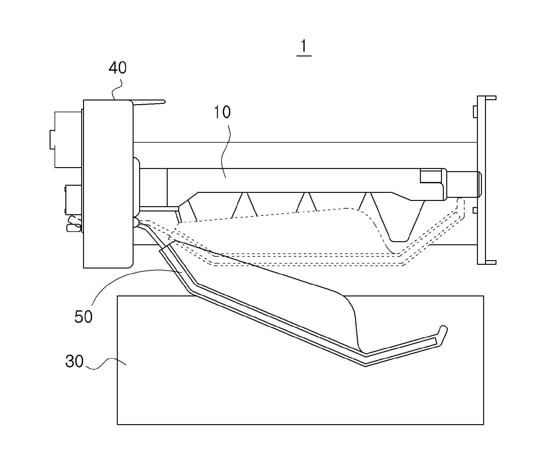
  • Driving device of icemaker for refrigerator
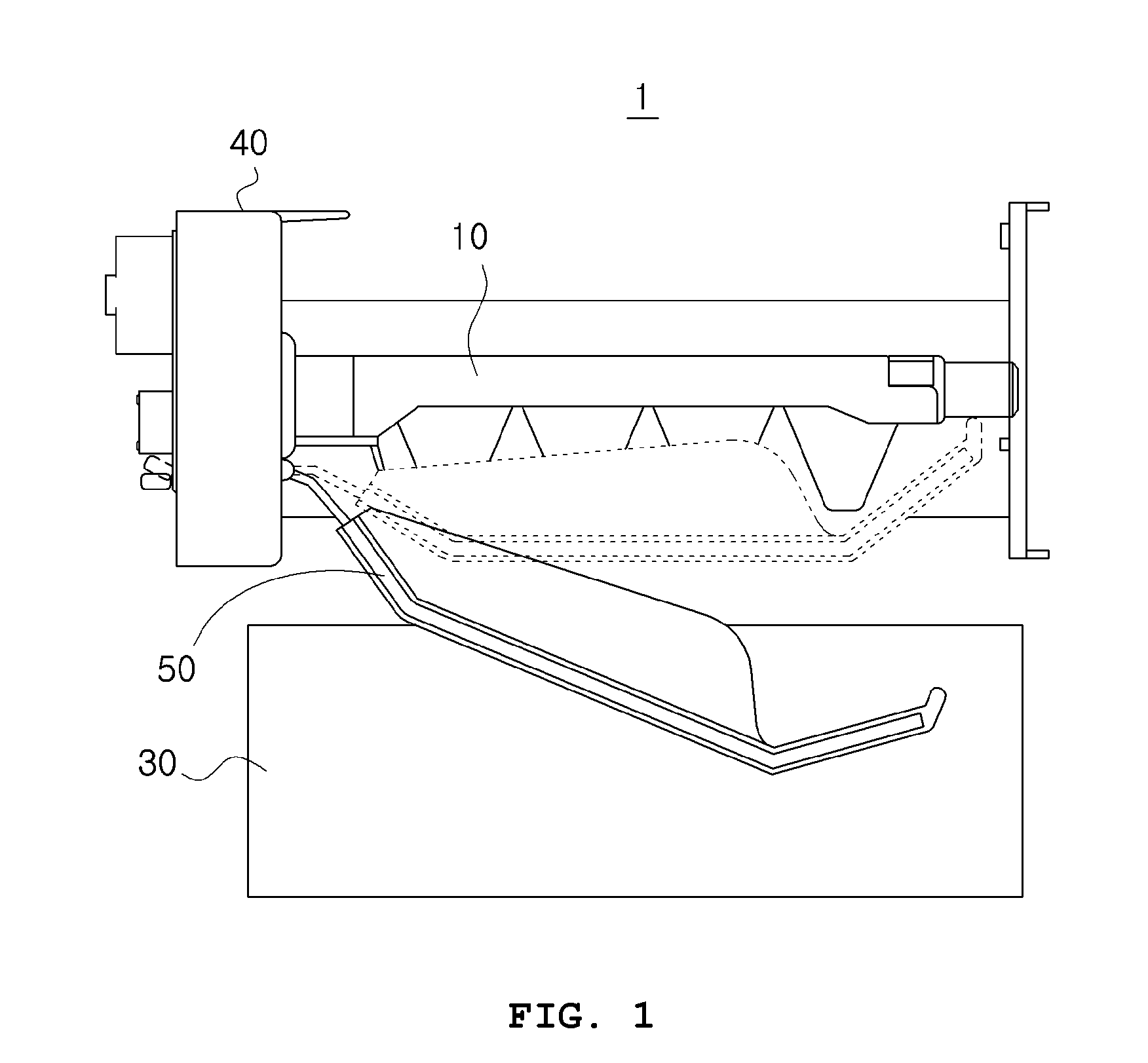
  • Driving device of icemaker for refrigerator
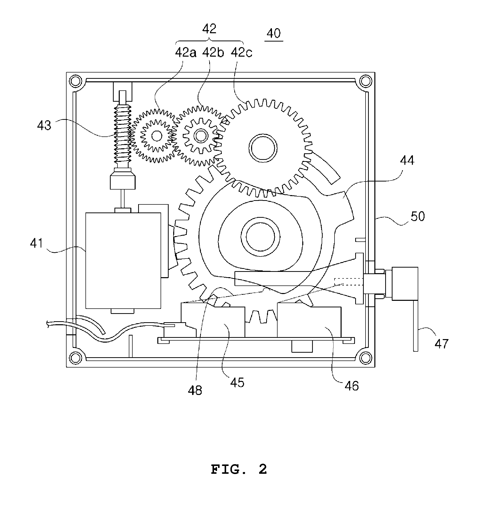
  • Driving device of icemaker for refrigerator

Examples


Embodiment Construction

[0033]The present invention may include various modifications and various embodiments, and thus specific embodiments will be illustrated in the drawings and described in the detailed descriptions. However, the present invention is not limited to specific embodiments, and may include all of variations, equivalents, and substitutes within the scope of the present invention.

[0034]Hereafter, embodiments of the present invention will be described in detail with reference to the accompanying drawings. Furthermore, regardless of reference numerals, like reference numerals will denote the same or corresponding components, and the duplicated descriptions thereof will be omitted. Furthermore, the terms such as up, down, left, right, front, and back, which indicate directions or positions, are used on the basis of the accompanying drawings.

[0035]Hereafter, a driving device of an icemaker for refrigerator in accordance with an embodiment of the present invention will be described with reference...


PUM


Abstract

A driving device of an icemaker for refrigerator may include: a driving device case coupled to an ice-making tray having an ejector rotating shaft coupled thereto; and a driving module housed in the driving device case so as to rotate the ejector rotating shaft.

Description

CROSS-REFERENCE TO RELATED APPLICATIONS[0001]This application is a Continuation-in-part of application Ser. No. 14 / 379,860, filed on Aug. 20, 2014. Furthermore, this application claims the benefit of priority of Korean application 10-2012-0024417, filed Mar. 9, 2012, the subject matter of which is incorporated by reference.TECHNICAL FIELD[0002]The present invention relates to an icemaker for refrigerator, and more particularly, to a driving device of an icemaker for refrigerator.BACKGROUND[0003]In general, a refrigerator refers to a home appliance which includes a storage room for storing food and a cold air supply device for supplying cold air to the storage room, in order to keep food fresh. Recently, an icemaker for refrigerator has been installed in a refrigerator, for a user's convenience. The icemaker directly freezes an ice-making tray to make ice, or supplies external cold air to the ice-making tray to make ice.[0004]Korean Patent Laid-open Publication No. 10-1998-026431 dis...

Claims


Application Information

Patent Timeline
IPC IPC(8): F25C1/10
CPCF25C2305/022F25C1/10F25C1/04F25C2305/024
Inventor LEE, JIN HO
Owner SCD CO LTD
Learn More