Obstacle detection system and method therefor

a detection system and obstacle technology, applied in the field of obstacles detection systems, can solve the problems of low detection accuracy of obstacles, high cost and impracticality of laser beam technology, and low resolution of ultrasonic wave technology, and achieve the effect of low measurement accuracy and high pri

Inactive Publication Date: 2005-11-08
TOSHIBA ELECTRONICS DEVICES & STORAGE CORPORARTION +1
View PDF4 Cites 103 Cited by
  • Summary
  • Abstract
  • Description
  • Claims
  • Application Information

AI Technical Summary

Problems solved by technology

The technology utilizing the laser beam costs high and is impractical.
On the other hand, the technology utilizing the ultrasonic waves has a low resolution so that it is troubled by the detection precision of the obstacle.
However, there are many obstacles having intensities, colors or textures similar to those of the ground.
Therefore, this method finds it difficult to separate the obstacle region and the ground region under the general situations.
It is difficult for the method using the single camera to detect the region having intensities, colors and textures similar to those of the ground, as the obstacle.
However, these operations require a long time and many works to obstruct the practical obstacle detection by the stereo vision.
The ordinary stereo method requires the search for matching points between the left and right images so that its computation cost is high because the correspondence is made by the search computation.
However, the aforementioned method requires no correspondence search so that the computational cost is extremely inexpensive.
It is, however, difficult to extract the numerous featuring points on the ground plane, and it frequently occurs that the featuring points on the obstacle are erroneously extracted.
Moreover, the correspondence search of the extracted featuring points has to be performed to raise the computation cost.
Also, with the large number of parameters to be determined, there has been a problem that it is seriously difficult to determine the ground plane constraint stably.

Method used


Image

  • Obstacle detection system and method therefor
  • Obstacle detection system and method therefor
  • Obstacle detection system and method therefor

Examples


embodiment 1

[0166]Embodiment 1 of the invention will be described with reference to the accompanying drawings.

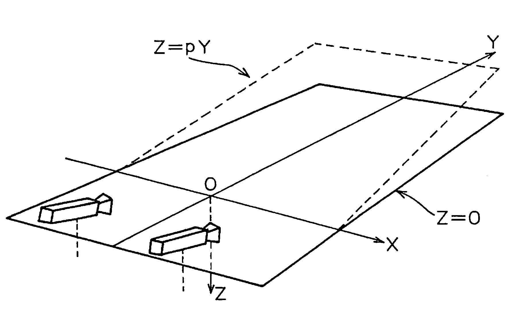
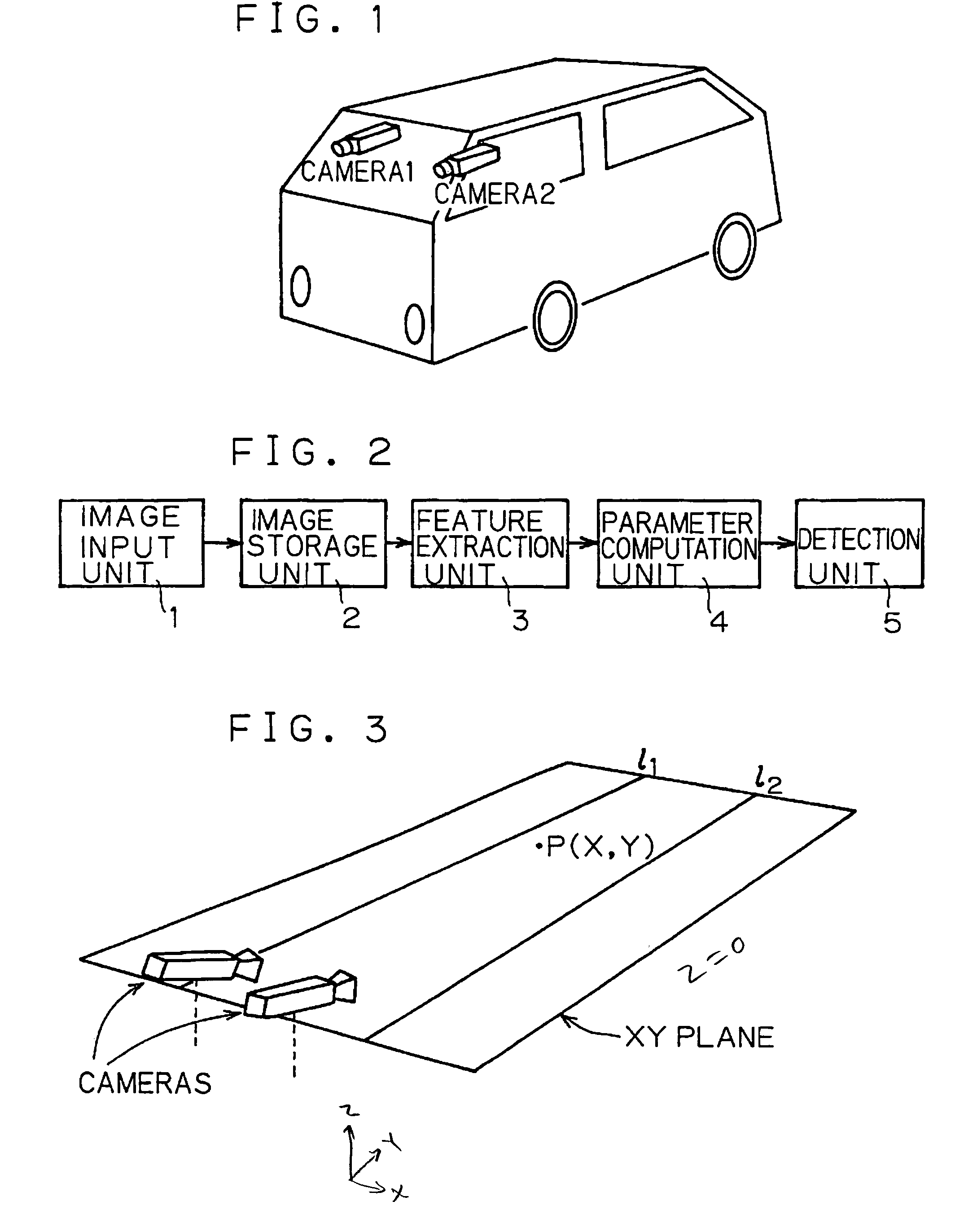
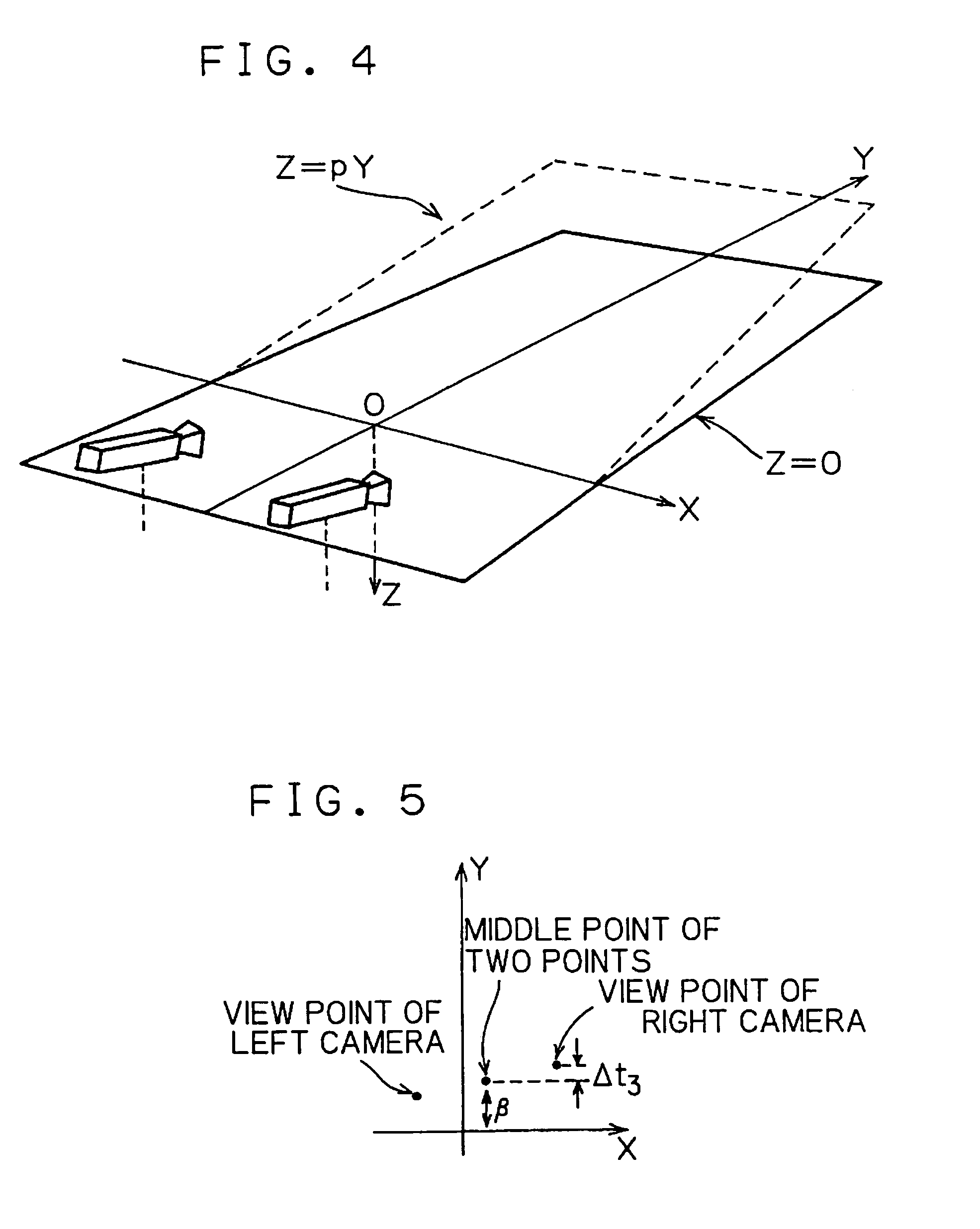
[0167]In this Embodiment, there is imagined a situation that an obstacle existing on a ground plane such as a pedestrian, a preceding vehicle or a parked vehicle is detected by two left and right stereo cameras mounted on a vehicle, as shown in FIG. 1.

[0168]FIG. 2 shows a schematic construction of the obstacle detection system according to this Embodiment. This obstacle detection system is constructed to include an image input unit 1, an image storage unit 2, a feature extraction unit 3, a parameter computation unit 4 and a detection unit 5. The obstacle detection system predetermines, in a still state, a relation (as will be called the “ground plane constraint”) to hold between the projected positions of a point of a ground plane upon left and right images, and computes the ground plane constraint at a traveling time, as changed time after time by the vibration of the driven vehicle an...

modification 1 — 1

Modification 1—1

[0198]In Embodiment 1, the image input unit 1 inputs two images by arranging the two TV cameras transversely, which may be vertically arranged.

[0199]On the other hand, there may be arranged three or more cameras.

modification 1-2

[0200]The feature extraction unit 3 has been described on the case in which the two lines on the ground plane are to be extracted, but three or more lines may be extracted.


PUM


Abstract

An obstacle detection system using stereo cameras mounted on a vehicle, to detect an obstacle existing on a ground plane at a high speed and in a high precision even with the stereo cameras being uncalibrated and with a vibration during a traveling and a change in the inclination of the ground plane. The obstacle detection system comprises: a plurality of uncalibrated TV cameras for inputting stereo images; an image storage unit 2 for storing a plurality of images inputted from the TV cameras; a feature extraction unit 3 for extracting a plurality of mutually parallel lines existing on the ground plane; a parameter computation unit 4 for determining a relation to hold between the projected positions of an arbitrary point of the ground plane upon the individual images, from the plurality of lines extracted by the feature extraction unit 3; and a detection unit 5 for detecting an object having a height from the ground plane, by using the relation determined by the parameter computation unit 4.

Description

BACKGROUND OF THE INVENTION[0001]1. Technical Field[0002]The present invention relates to an obstacle detection system for detecting an obstacle existing on a ground, such as a preceding vehicle, a pedestrian or a parked vehicle with cameras mounted on a vehicle, so as to support the safe drive of an automobile.[0003]2. Background Art[0004]The technology for detecting an obstacle with a sensor is coarsely divided into one utilizing a laser beam or ultrasonic waves and one utilizing TV cameras. The technology utilizing the laser beam costs high and is impractical. On the other hand, the technology utilizing the ultrasonic waves has a low resolution so that it is troubled by the detection precision of the obstacle.[0005]On the contrary, the TV cameras are relatively inexpensive so that they are suitable for the obstacle detection from the aspects of the resolution, the measuring precision and the measuring range. In the case of using the TV cameras, there are methods of employing one ...

Claims


Application Information

Patent Timeline
Patent Type & Authority Patents(United States)
IPC IPC(8): G06K9/00B60R1/00G06T7/00G06V10/147
CPCB60R1/00G06K9/209G06K9/3241G06T7/0075G06K9/00805G06K2209/23G06T2207/10012G06T2207/30261G06T7/593G06V20/58G06V10/147G06V10/255G06V2201/08
Inventor HATTORI, HIROSHIONOGUCHI, KAZUNORITAKEDA, NOBUYUKI
Owner TOSHIBA ELECTRONICS DEVICES & STORAGE CORPORARTION
Why Eureka
Try Eureka