Electronic apparatus having improved diagnostic interface

a technology of electronic equipment and diagnostic interface, which is applied in the field of personal computers, can solve the problems of inability to determine the source of the problem or how to solve, failure during execution of post indicates presence of a fault within the computer, and the internal complexity of the personal computer system itself has also greatly increased, so as to facilitate the overall support process

Inactive Publication Date: 2005-11-08
HEWLETT-PACKARD ENTERPRISE DEV LP
View PDF10 Cites 7 Cited by
  • Summary
  • Abstract
  • Description
  • Claims
  • Application Information

AI Technical Summary

Benefits of technology

[0028]In a particularly preferred arrangement, the database query is transmitted over the internet to a database maintained separately from the call handling system. The database can be, for instance, maintained by or on behalf of the manufacturer of the computer and include all machines sold by that manufacturer. The call handling system can be maintained by a third party that is granted access to the database. This relieves the party offering the support services from the substantial burden of having to maintain the database.
[0029]The fact that, in event of a fault with the computer, a parameter can be transmitted from the computer, automatically decoded and the used as key to retrieve fuller information regarding the computer concerned from a centrally maintained database greatly facilitates the overall support process. With the above described arrangement, this can be achieved even if the main processing functionality of the computer is not operational.

Problems solved by technology

Whilst improvements are continually being made in the user interfaces of personal computers in order to make them usable by a wider cross section of the population, personal computer systems themselves have also greatly increased in their internal complexity so that today most users are unfamiliar with the internal design and configuration of the computers that they use.
In consequence, when a computer fails to operate in the manner expected, the user is often unable to determine the source of the problem or how to resolve it.
Failure during execution of POST indicates presence of a fault within the computer.
However, POST does not always provide a clear indication of the specific nature of the fault.
However, the inclusion of a separate microprocessor, together with its own user interface, adds a significant cost to the computer as a whole.
Moreover, much of the information contained within the diagnostic programs and manuals is often beyond the understanding of the average user and therefore when faced with a problem, the user may need to or may prefer to call the computer manufacturer's customer service line or help desk in order to obtain technical help.
This process is often slow and unsatisfactory.
The amount of time required for the user to accurately describe the problem to the help desk representative is often considerable.
It is also frequently plagued by inaccurate instructions being conveyed to the user over the phone.
It is not possible to dictate a full log file over the phone, so often the user is asked to transmit these data over email or fax and to call back later.
On the second call it is difficult to establish a link between the call and the email or fax received especially when it is necessary to transfer the call through an automatic routing system.
To compound the communication difficulties described above, diagnostic routines are often invoked when components in the computer are not completely functional and so the diagnostics may not execute or interact properly with the computer or with the user.
However, this system requires the computer to boot correctly and be substantially fully operational before the audible tones can be generated.

Method used


Image

  • Electronic apparatus having improved diagnostic interface
  • Electronic apparatus having improved diagnostic interface
  • Electronic apparatus having improved diagnostic interface

Examples


Embodiment Construction

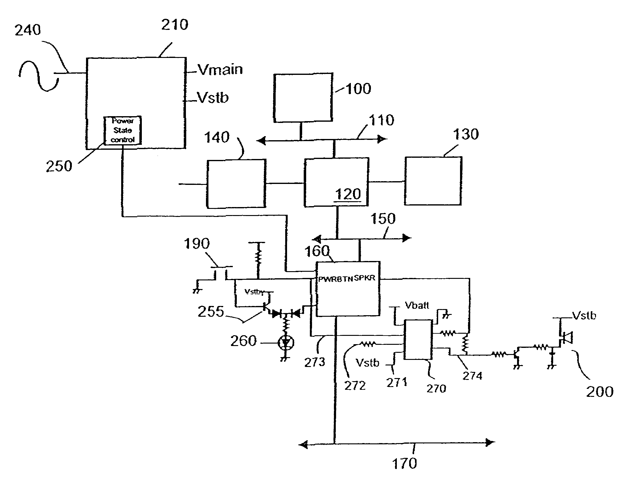
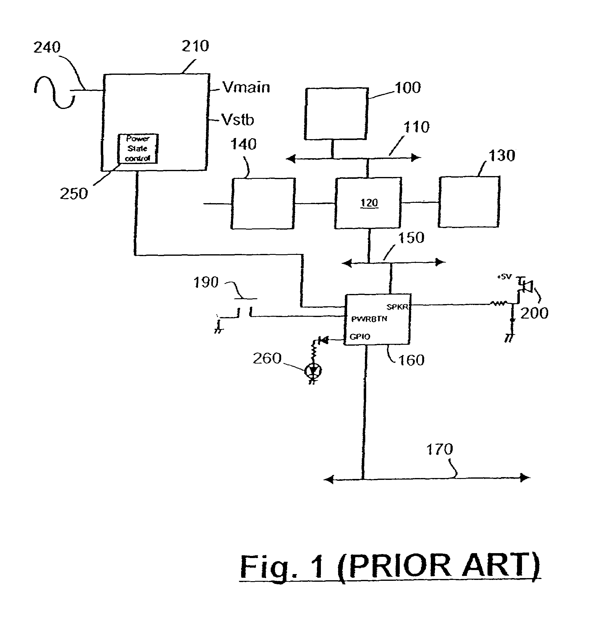
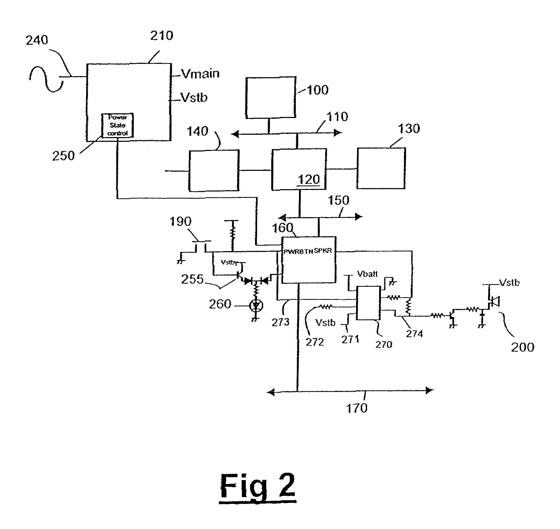
[0036]FIG. 1 is a schematic diagram showing, in relevant part, the architecture of a personal computer. A microprocessor 100 is connected via host bus 110 to a so-called ‘North Bridge’ chipset device 120. Chipset device 120 has interfaces to a DRAM memory device 130, a graphics subsystem 140 and a PCI bus 150. Connected to PCI bus 150 is a so-called ‘South Bridge’ chipset component 160, that provides an interface between PCI bus 150 and ISA bus 170 as well as other functionality. Various of the components including DRAM 130, chipset component 160 and a number of sensors (not shown) are interconnected by a separate two wire bus(not shown), known as the System Management bus (SMBus). The function of the SMBus is to allow system components such as cooling fans to be centrally controlled, and to provide a feedback channel for information on the physical conditions within the PC, such as temperature, to be passed back to the chipset. The chipset can then take appropriate corrective or ma...


PUM


Abstract

Electronic apparatus, such as a personal computer, is described comprising main operative functionality and a power provisioning system for powering the apparatus from an external power source, the power provisioning system comprising:—a main power supply output for energizing the main operative functionality of the apparatus when said power provisioning system is connected to said external power source, and a standby power source for energizing a subset of the components of the apparatus when said main power supply output is not energized, the apparatus further comprising a self contained subsystem including a memory for storing at least one parameter reflecting an internal state of the apparatus, said self contained subsystem being powered by said standby power source and including an encoder for encoding the parameters in an output signal and a transducer for generating a wireless transmission from the output signal, which transmission can be detected in the vicinity of the apparatus, so as to enable the parameter to be received and decoded.

Description

RELATED APPLICATIONS[0001]This patent application is a divisional application of U.S. Ser. No. 09 / 511,342, filed on Feb. 23, 2000, now U.S. Pat. No. 6,662,316.FIELD OF THE INVENTION[0002]The present invention relates to a personal computer, or other similar electronic apparatus, having an improved diagnostic interface.BACKGROUND OF THE INVENTION[0003]Personal computers are being used in an increasing number of applications. Whilst improvements are continually being made in the user interfaces of personal computers in order to make them usable by a wider cross section of the population, personal computer systems themselves have also greatly increased in their internal complexity so that today most users are unfamiliar with the internal design and configuration of the computers that they use. In consequence, when a computer fails to operate in the manner expected, the user is often unable to determine the source of the problem or how to resolve it.[0004]Various means are provided to e...

Claims


Application Information

Patent Timeline
Patent Type & Authority Patents(United States)
IPC IPC(8): G06F1/28G06F1/26G06F11/00G06F1/30G06F11/22G06F11/273H02H3/05H04M11/00
CPCG06F11/0748G06F11/2294
Inventor OWHADI, ERIC
Owner HEWLETT-PACKARD ENTERPRISE DEV LP
Why Eureka
Try Eureka