Utility knife

a technology of utility knives and blades, applied in the field of utility knives, can solve the problems of difficult to properly mount the blade within the components of the case, frequent accidents, and inability to fully satisfy the user,

Inactive Publication Date: 2005-11-22
REPETTO LLC
View PDF28 Cites 56 Cited by
  • Summary
  • Abstract
  • Description
  • Claims
  • Application Information

AI Technical Summary

Problems solved by technology

In most utility knives, reversal of the blade requires handling of it, and because the blades are very sharp, thin, and not particularly easy to handle, accidents frequently occur.
It is also difficult to properly mount the blade within the components in the case.
A number of utility knives have been developed that employ cartridges that hold a plurality of blades, some of which enable the user to change the blade with a reduced risk of cutting ones self, but none have proved to be entirely satisfactory.
Some require a very large case to receive the cartridge, which detracts from the comfort of using the tool.
And none of the prior art tools known to applicant provide total protection against accidental injury when reversing or changing the blade.
Many of those knives have non-traditional shapes so as to limit their appeal to those who frequently use them.

Method used


Image

  • Utility knife
  • Utility knife
  • Utility knife

Examples


case 40

Case 40

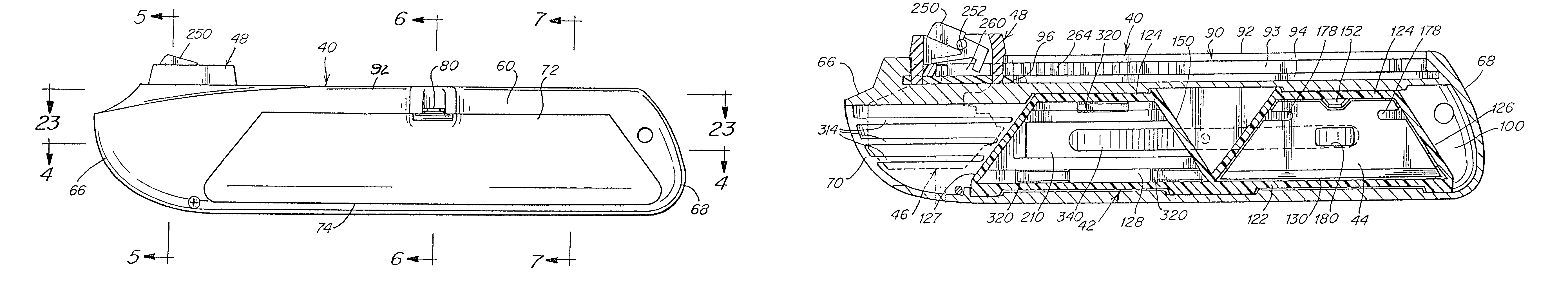
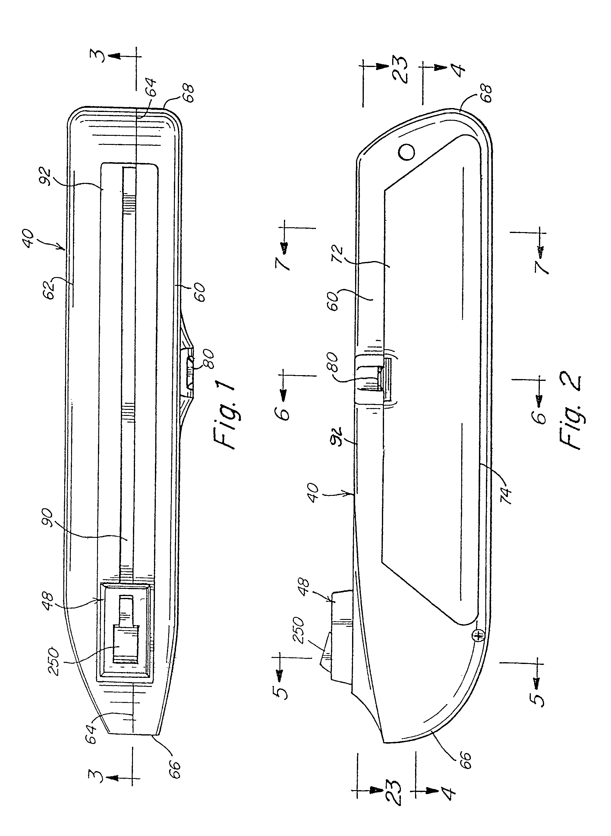
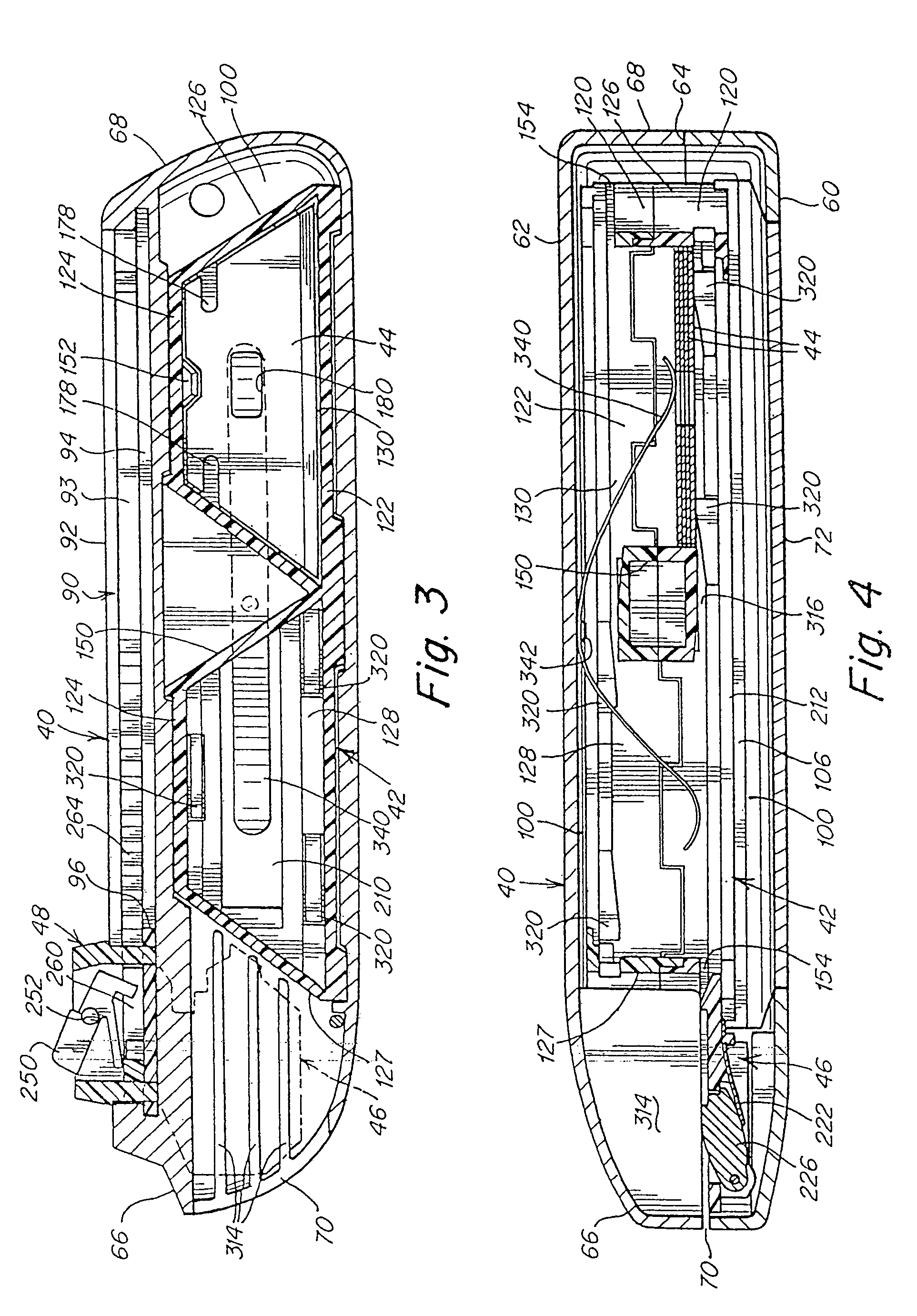
[0039]The case 40 is particularly illustrated in FIGS. 1–8. The case in the illustrated embodiment typically is a metal casting such as die casting of aluminum or zinc and is composed of two halves or shells 60 and 62 that may be secured together by any one or more of a variety of different fasteners such as screws, hook-like fingers, snaps, etc. to form an elongated housing for the utility knife components as well as a handle for operating the knife. In FIGS. 1 and 5–7, parting lines 64 along the top and bottom are suggested representing the mating edges of the two halves 60 and 62 of the case. In this description the end 66 of the case will sometimes be identified as the front end while the other end 68 will sometimes be identified as the back end of the case. The parting line 64 of the case runs longitudinally from end-to-end, and in the usual orientation of the case illustrated, is in a vertical plane. The front end of the case 66 has a blade slot 70 (see FIG. 4) through ...


PUM


Abstract

A utility knife has a disposable blade cartridge in its handle that has front and rear blade compartments. Each compartment is sized to store a plurality of blades in side-by-side relation. Fresh blades are disposed in the front compartment and one end of each is advanced one at a time substantially out of the compartment into operative position by a carrier that is controlled by an actuator on the handle. When the active blade is to be replaced, it is moved by the carrier into the rear compartment, and a new blade may then be withdrawn from the front compartment into the operative position. The active blade when not in use is partially withdrawn into the front compartment. The cartridge is reversed when the one end of all the blades in the front compartment are used, placing what was the rear compartment at the front, and the unused end of each blade is advanced into the operative position and when used they are each moved to the rear compartment. When all are used, a new cartridge replaces the old in the knife

Description

FIELD OF THE INVENTION[0001]This invention relates to utility knives and more particularly comprises a utility knife with an automatic blade loading system that enables the user to change blades without touching them so as to achieve maximum safety, speed and convenience in the operation of the device. This application claims the benefits of applicant's earlier filed, copending provisional application Ser. No. 60 / 307,285 filed Jul. 23, 2001 and incorporated herein by reference.BACKGROUND OF THE INVENTION[0002]Utility knives are widely used for a number of different purposes and are a very popular and handy tool. Conventionally, utility knives use a thin double-ended blade that in use extends out one end of the knife case. When the cutting end becomes dull or otherwise unsuited for continued use, the blade is reversed so that its other end extends out of the case. In most utility knives, reversal of the blade requires handling of it, and because the blades are very sharp, thin, and n...

Claims


Application Information

Patent Timeline
Patent Type & Authority Patents(United States)
IPC IPC(8): B26B5/00
CPCB26B5/001
Inventor FOSSELLA, GREGORY
Owner REPETTO LLC
Why Eureka
Try Eureka