
Multi-functional electric stepper motor assembly having increased motor torque

Active Publication Date: 2005-11-22
NOVANTA CORP
View PDF4 Cites 4 Cited by
  • Summary
  • Abstract
  • Description
  • Claims
  • Application Information

AI Technical Summary

Benefits of technology

[0005]An electric stepper motor with increased motor torque includes a thru-hole, a rotor and a stator. The stator is internally arranged within the rotor assembly and the rotor assembly consists of a permanent magnet with a first pair of rotor cups and a second pair of rotor cups. The first and second pair of rotor cups are separated via a non-magnetic spacer. The thru-hole allows use with a chamber and provides transport of hardware and elements into the chamber.

Problems solved by technology

Current step motor designs do not easily adapt to such through motor applications without substantial modification.

Method used


Image

  • Multi-functional electric stepper motor assembly having increased motor torque
  • Multi-functional electric stepper motor assembly having increased motor torque
  • Multi-functional electric stepper motor assembly having increased motor torque

Examples


Embodiment Construction

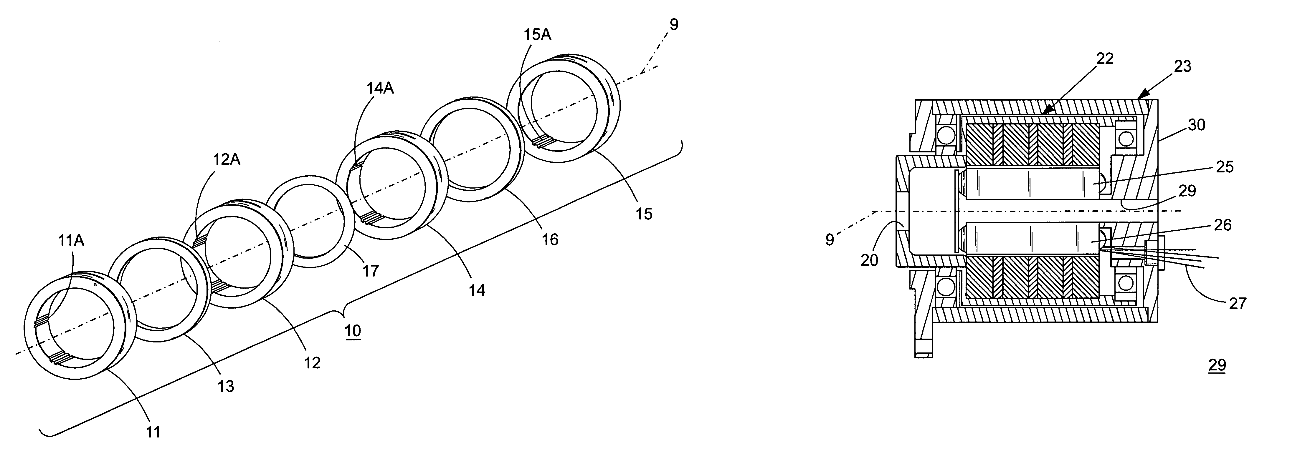
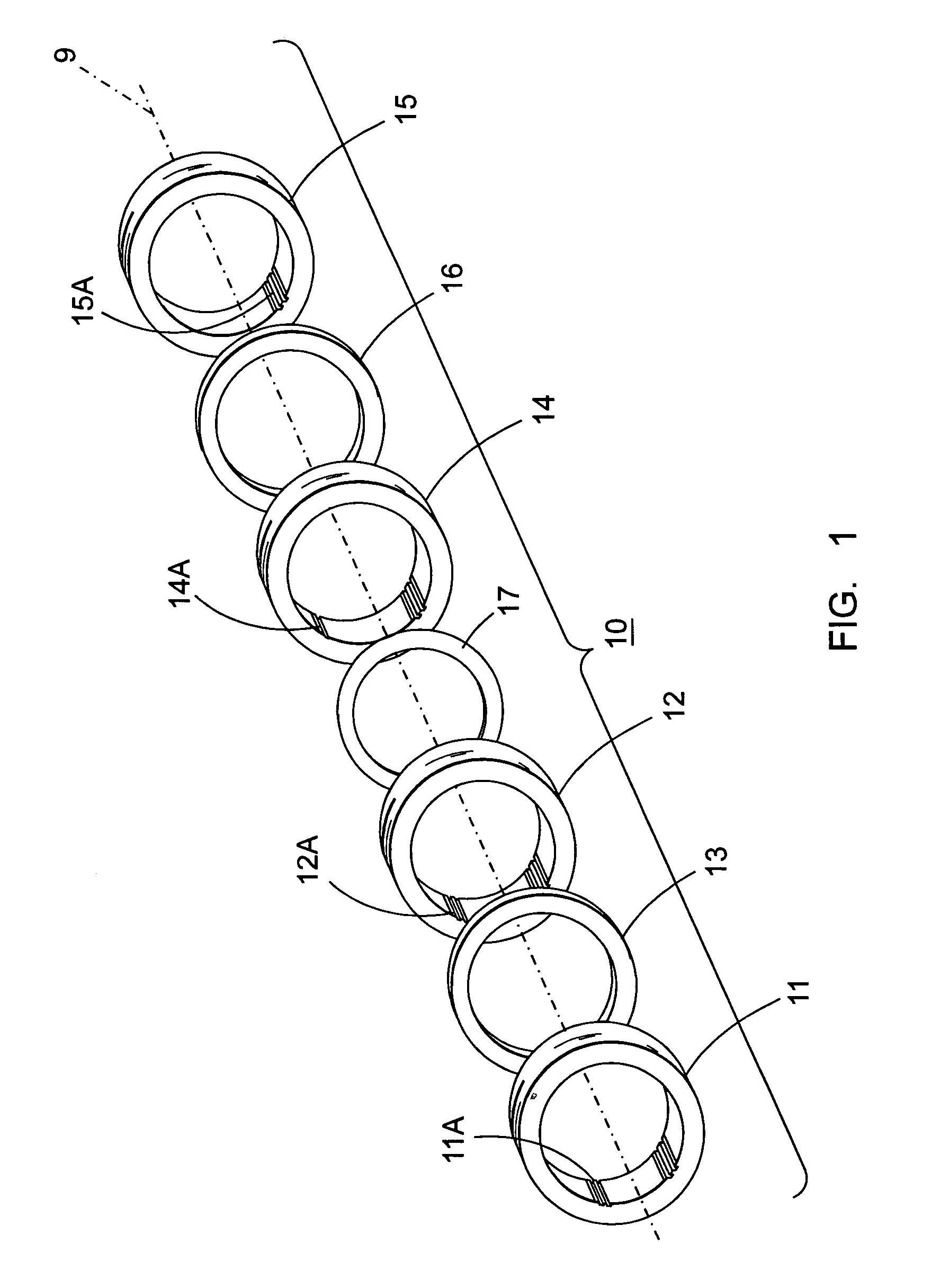
[0009]FIG. 1 depicts the increased stepper motor torque rotor assembly 10 consisting of a first pair of rotor cups 11, 12 having interior laminations 11A, 12A similar to those described in the aforementioned U.S. Pat. No. 6,002,186 and separated by means of a first thin magnetic cylinder 13. The increased motor torque rotor assembly 10 further includes a second pair of rotor cups 14, 15, having similar interior laminations 14A, 15A separated by a second thin magnetic cylinder 16 and are arranged concentric with a common centerline as shown at 9. The first pair of rotor cups 11, 12 and second pair of rotor cups 14, 15 are in turn separated by means of the non-magnetic spacer disc 17 whereby the resulting first and second magnetic fields (not shown) generated by the first and second pair of rotor cups 11, 12, 14, 15 additively combine to produce increased motor torque without interfering with the individual first and second magnetic fields, per se.

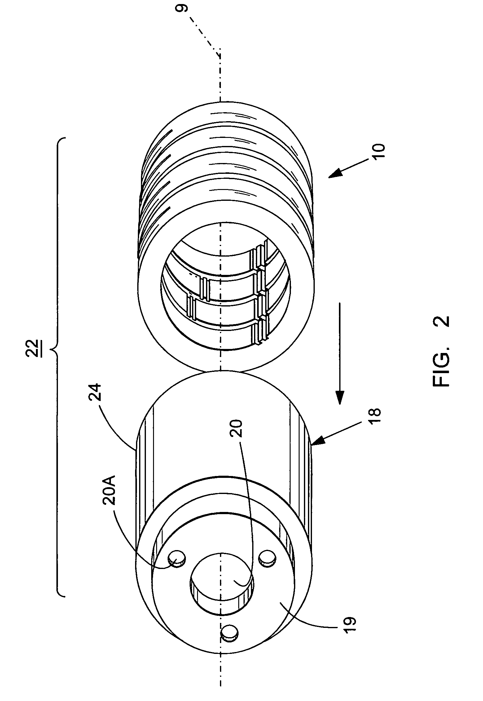
[0010]Referring now to FIG. 2, the in...


PUM


Abstract

An electric stepper motor having increased motor torque includes a thru-hole, a rotor and a stator. The thru-hole allows use with a chamber and provides transport of hardware and elements into the chamber. A first and second pair of rotor cups separated by a non-magnetic spacer disc provide increased motor torque.

Description

BACKGROUND OF THE INVENTION[0001]There exists a need in motion control applications for the use of stepper motors as through-hole motors in semiconductor, manufacturing and medical processes that use light emitted by lasers, radar positioning pedestals, and environmentally controlled chambers. Current step motor designs do not easily adapt to such through motor applications without substantial modification.[0002]One example of a stepper motor having an internal opening is found in U.S. Pat. No. 6,002,186 entitled Electrical Stepper Motor Having a Cylindrical Magnetic Rotor within a Pair of Cups of Magnetic Material”.[0003]The advent of such a stepper motor having an internal opening for semiconductor, manufacturing and medical applications, has occasioned demand for such motors having higher power applications, not achievable by the power rating of the aforementioned U.S. Pat. No. 6,002,186.[0004]One purpose of the invention is to describe a stepper motor having an internal opening ...

Claims


Application Information

Patent Timeline
IPC IPC(8): H02K1/22H02K37/00H02K21/00H02K1/27H02K1/28H02K5/173H02K37/12
CPCH02K1/2786H02K1/28H02K5/1732H02K37/12H02K1/2788
Inventor BENNETT, ALLEN
Owner NOVANTA CORP
Features
  • Generate Ideas
  • Intellectual Property
  • Life Sciences
  • Materials
  • Tech Scout
  • Unparalleled Data Quality
  • Higher Quality Content
  • 60% Fewer Hallucinations
Learn More