Rotor and motor
A technology of rotor and rotor core, which is applied to rotating parts of magnetic circuit, synchronous motors with stationary armatures and rotating magnets, electromechanical devices, etc. To achieve the effect of increasing the motor torque
- Summary
- Abstract
- Description
- Claims
- Application Information
AI Technical Summary
Problems solved by technology
Method used
Image

Examples
no. 1 Embodiment approach >
[0023]
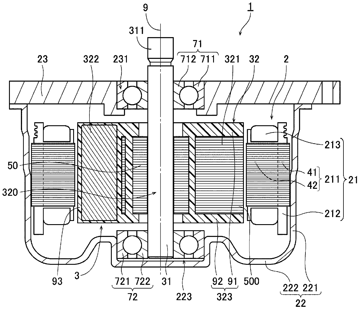
[0024] figure 1 It is a vertical sectional view of the motor 1 of the first embodiment. The motor 1 is used in home appliances such as air conditioners and washing machines, for example. However, the motor 1 of the present invention can also be used for applications other than home electric appliances. For example, the motor 1 of the present invention may be mounted on transportation equipment such as automobiles and railcars, OA equipment, medical equipment, tools, large industrial equipment, etc., to generate various driving forces.
[0025] This motor 1 is a so-called inner rotor type motor in which a rotor 32 is disposed radially inside of a stator 21 . Such as figure 1 As shown, the motor 1 has a stationary part 2 , a rotating part 3 , an upper bearing part 71 and a lower bearing part 72 . The stationary unit 2 is fixed to the housing of the device on which the motor 1 is mounted. The rotating part 3 is supported so as to be rotatable about the center axis...
no. 2 Embodiment approach >
[0054] Next, a second embodiment of the present invention will be described. In addition, the following description will focus on differences from the first embodiment, and redundant description of the same parts as in the first embodiment will be omitted.
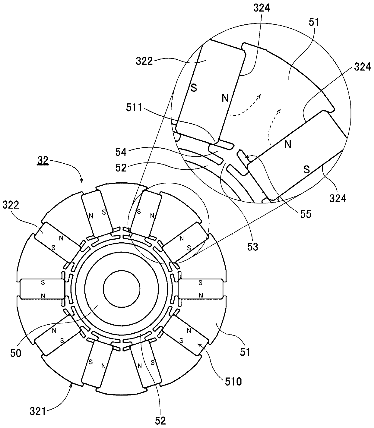
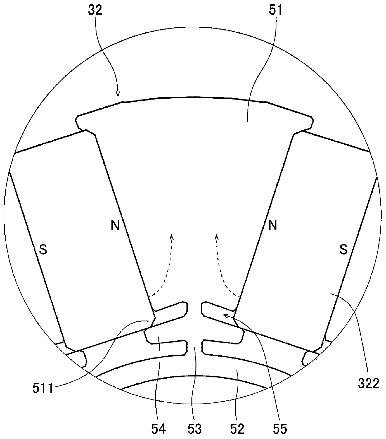
[0055] Figure 6 It is a plan view of the rotor 32B of the second embodiment. But when Figure 6 In , the illustration of the resin part is omitted. Figure 7 It is a partial plan view of the rotor 32B of the second embodiment. Such as Figure 6 and Figure 7 As shown, the rotor 32B has a rotor core 321B, a plurality (ten in this embodiment) of magnets 322B, and a resin portion. But when Figure 6 and Figure 7 In , the illustration of the resin part is omitted.
[0056] The rotor core 321B has an inner core portion 50B, a plurality (ten in this embodiment) of core magnetic pole portions 51B, a circumferential connection portion 52B, and a plurality (ten in this embodiment) of radial connection portions. part 53B...
PUM
 Abstract
Description
Claims
Application Information