
Lens assembly with externally adjustable lens spacing, and method for its assembly

Active Publication Date: 2005-11-22
RAYTHEON CANADA LTD
View PDF7 Cites 2 Cited by
  • Summary
  • Abstract
  • Description
  • Claims
  • Application Information

AI Technical Summary

Benefits of technology

[0006]The present invention provides a lens assembly and a method for its assembly. This approach achieves a precise optical spacing between lenses and other optical components without repeated disassembly, rework, and reassembly. It is therefore faster and more economical, and avoids random errors in reassembly that are associated with other techniques. When the required positionings are achieved, the lenses and other optical components may be fixed permanently or semi-permanently in place.
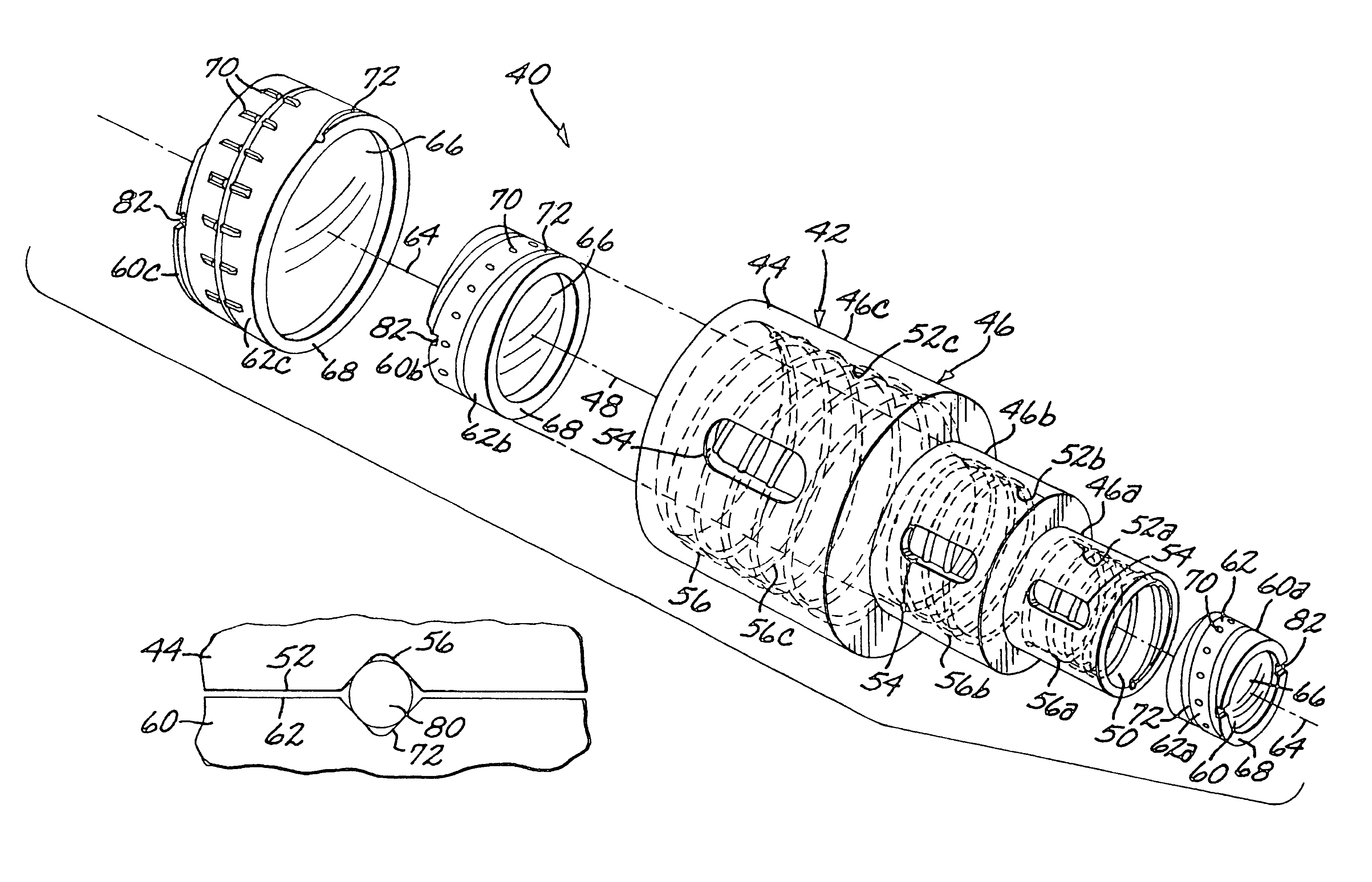
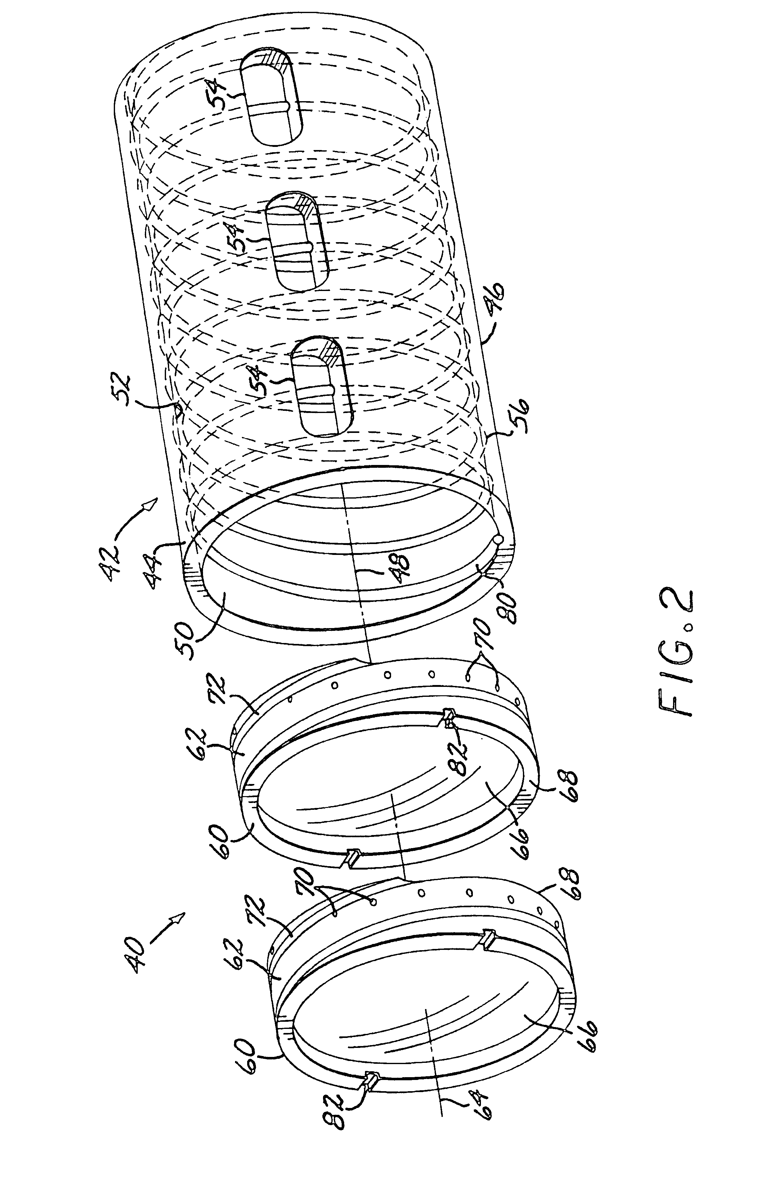
[0013]The present approach produces a highly precise spacing between a lens and other optical elements, such as between two or more lenses. There is no repeated disassembly, reworking, and reassembly that can produce random errors. The adjustments in the axial position of the lens(es) are made through the access window(s) in the housing body, by turning the lens(es) on the engagement between the lens(es) and the interior helical recess of the housing body.
[0014]The thread wire serves both as the thread upon which the lens elements turn, and also as a spring bias to hold the lens elements in a play-free position and to avoid backlash upon reversal of the direction of the rotation of the lens element. With this configuration, the lens elements are held relatively securely and rigidly in place even before they are permanently or semi-permanently fixed in position at these same locations, so that optical performance measurements of the optical assembly are reliable indicators of the optical performance after the lens elements are permanently or semi-permanently fixed in place.
[0015]The present approach therefore reliably produces a more precise spacing between the lenses and other optical elements in the lens assembly. It is also significantly faster and more economical in producing the precise spacing than are conventional methods, and in reaching the final lens assembly.

Problems solved by technology

However, it is slow, tedious, and uneconomic.
It may also have significant technical problems.
Upon each disassembly and reassembly, there may be a random error that introduces uncertainty as to whether the subsequent measurements and adjustments will be effective in producing the required optical performance.
There is also a possibility of damage to the lenses or the housing at each disassembly / reassembly iteration.

Method used


Image

  • Lens assembly with externally adjustable lens spacing, and method for its assembly
  • Lens assembly with externally adjustable lens spacing, and method for its assembly
  • Lens assembly with externally adjustable lens spacing, and method for its assembly

Examples


Embodiment Construction

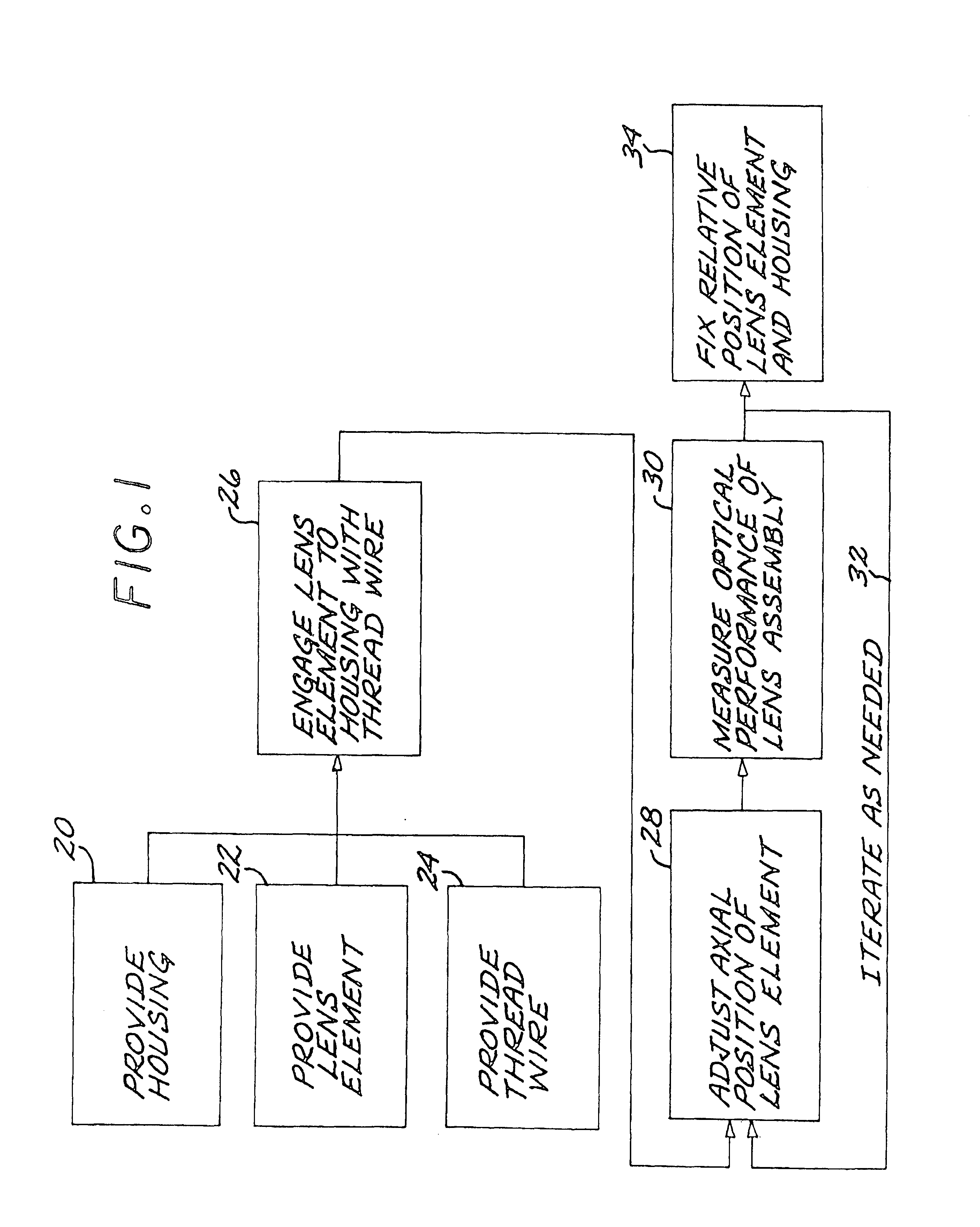
[0021]FIG. 1 depicts the steps in a method for assembling a lens assembly, and FIGS. 2 and 3 illustrate two embodiments of lens assemblies 40 that may be produced by this approach.

[0022]A housing 42 is provided, step 20. The housing 42 includes a housing body 44 that typically but not necessarily has a housing external surface 46 that is substantially cylindrical about a cylindrical housing axis 48. In the embodiment of FIG. 2, the housing external surface 46 is cylindrical with a single cylindrical diameter. In the embodiment of FIG. 3, the housing external surface 46 is cylindrical with a series of different segments 46a, 46b, and 46c, each with a different cylindrical diameter relative to the cylindrical housing axis 48. The housing 42 has a cylindrical bore 50 in the housing body 44 with an internal bore surface 52. In the embodiment of FIG. 2, the internal bore surface 52 is cylindrical with a single cylindrical diameter. In the embodiment of FIG. 3, the internal bore surface 5...


PUM


Abstract

A lens assembly includes a housing having a housing body, a cylindrical bore in the housing body with an internal bore surface and a cylindrical housing axis, at least one access window through the housing body that permits external access to an interior of the housing body, and an interior helical recess in the bore surface. A cylindrical lens element has an external cylindrical lens element surface received within the cylindrical bore of the housing and a cylindrical lens-element axis coincident with the cylindrical housing axis. The lens element includes a lens positioned perpendicular to the cylindrical lens-element axis, an adjustment engagement that is externally accessible through the access window of the housing, and an exterior helical recess in the external cylindrical lens element surface. The exterior helical recess has the same pitch as the interior helical recess and is in facing relation to the interior helical recess. The lens assembly is assembled and adjusted by rotatably engaging the interior helical recess and the facing exterior helical recess with a thread wire; and adjusting the axial position of the lens element by rotating the lens element relative to the housing body. The approach may be used with multiple lens elements.

Description

[0001]This invention relates to an optical system with a lens assembly and, more particularly, to the structure of the lens assembly and a method for its assembly and adjustment.BACKGROUND OF THE INVENTION[0002]Many optical systems using lens assemblies achieve acceptable optical performance with a standardized structure in which the lenses are supported on mounting surfaces in the lens housing. In this case, the housing and the lenses are manufactured to normal manufacturing tolerances, and the lenses are inserted into the housing and fixed in place without adjustment. On the other hand, high-performance optical assemblies having one or more lenses may require a level of optical performance beyond that achievable within normal manufacturing variations of the lenses and the lens housing. In this case, it may be necessary to axially adjust the positions of the lenses relative to each other during assembly in an iterative manner, until the required optical performance is achieved. The...

Claims


Application Information

Patent Timeline
IPC IPC(8): G02B7/02
CPCG02B7/021G02B7/023
Inventor DEVENYI, GABOR
Owner RAYTHEON CANADA LTD
Learn More