Two-part plastic snap hinge closure

a hinge closure and two-part technology, applied in the direction of closure lids, closure stoppers, caps, etc., can solve the problems of enormous capacity of such assembly machines, and achieve the effect of preventing large amounts of plastic material and cheapest possible production

Inactive Publication Date: 2005-12-06
TERXO
View PDF10 Cites 27 Cited by
  • Summary
  • Abstract
  • Description
  • Claims
  • Application Information

AI Technical Summary

Benefits of technology

[0011]In this regard, this invention has a completely different object. Longevity is of no real interest, but rather the cheapest possible production. Thus it is intended to prevent large amounts of plastic material from having to flow over thin places, for example film hinges.

Problems solved by technology

Although such a manufacture demands an additional assembly machine, it is known from analogous uses that the capacity of such assembly machines is enormously great.

Method used


Image

  • Two-part plastic snap hinge closure
  • Two-part plastic snap hinge closure
  • Two-part plastic snap hinge closure

Examples


first embodiment

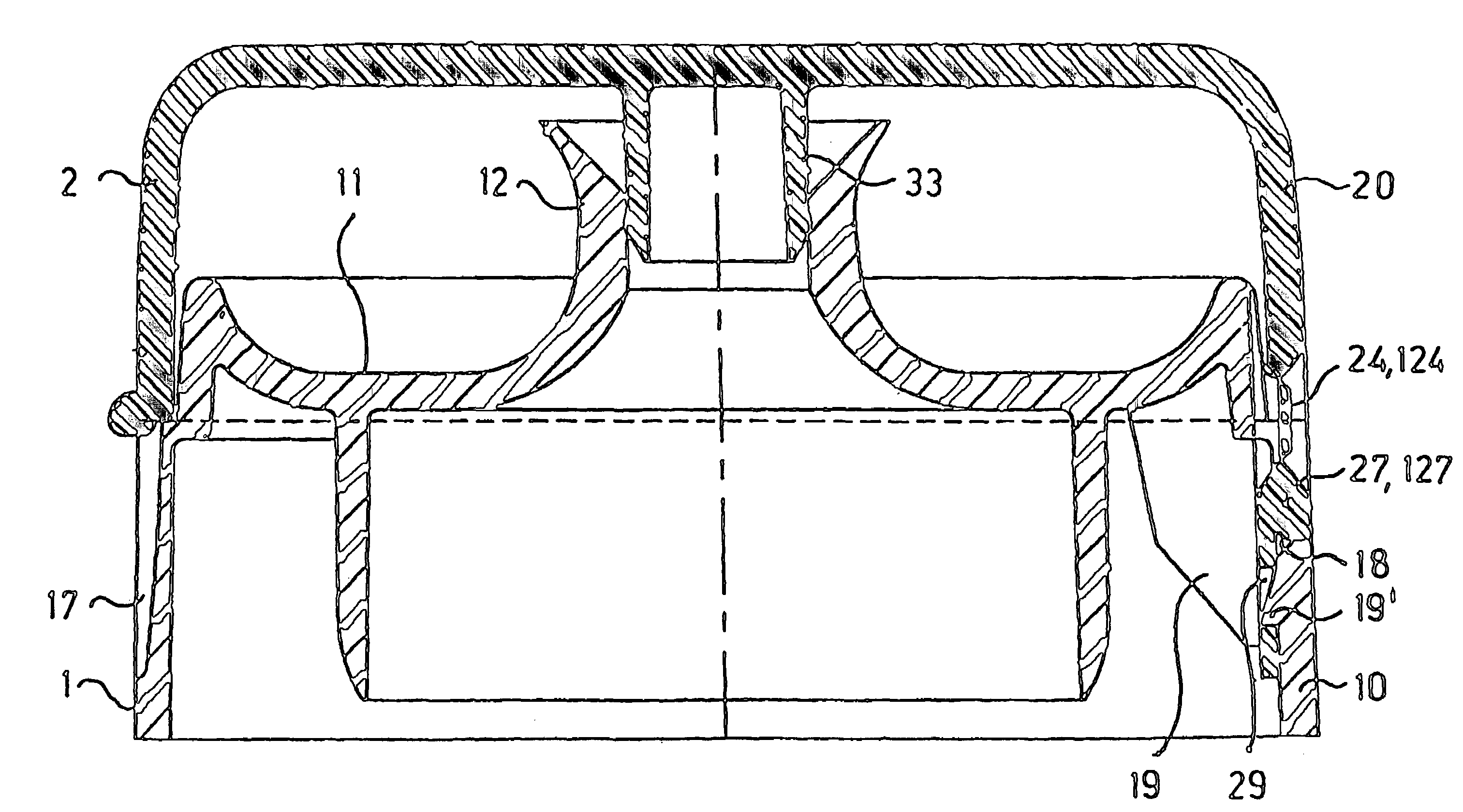
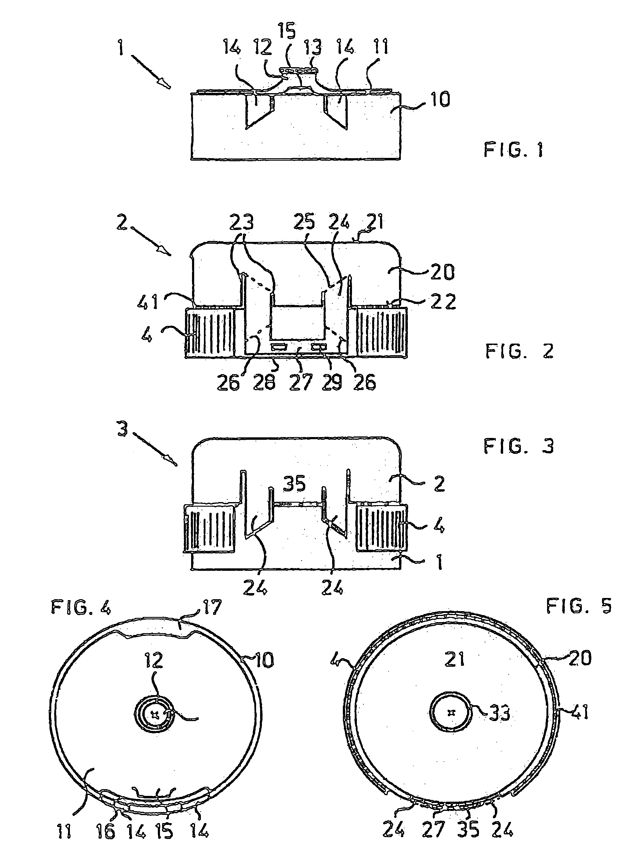
[0037]A first embodiment is represented in FIGS. 1 to 5. The lower closure part 1 in FIG. 1 has a cylindrical casing wall 10. The lower part 1 has fastening means with which the lower part 1 can be fastened on a container. The fastening means are conventional, for example, a screw thread arranged on the inner wall of the cylindrical casing wall 10, or fastening cams or fastening beads, depending on whether it is intended to screw or press the lower part 1 on a container.

[0038]On the top, the lower part 1 is closed off by a cover surface 11, in which a pouring opening or, as in this case a pouring spout 12, is arranged. In a conventional manner, the pouring spout has a circumferential sealing or holding bead 13. Recesses 14 are shown in the lateral view of FIG. 1, which permit the movable spring elements to be free. These cutouts are inwardly offset toward the center in relation to the outer surface of the casing wall 10. The recesses 14 can be offset so far toward the interior that ...

second embodiment

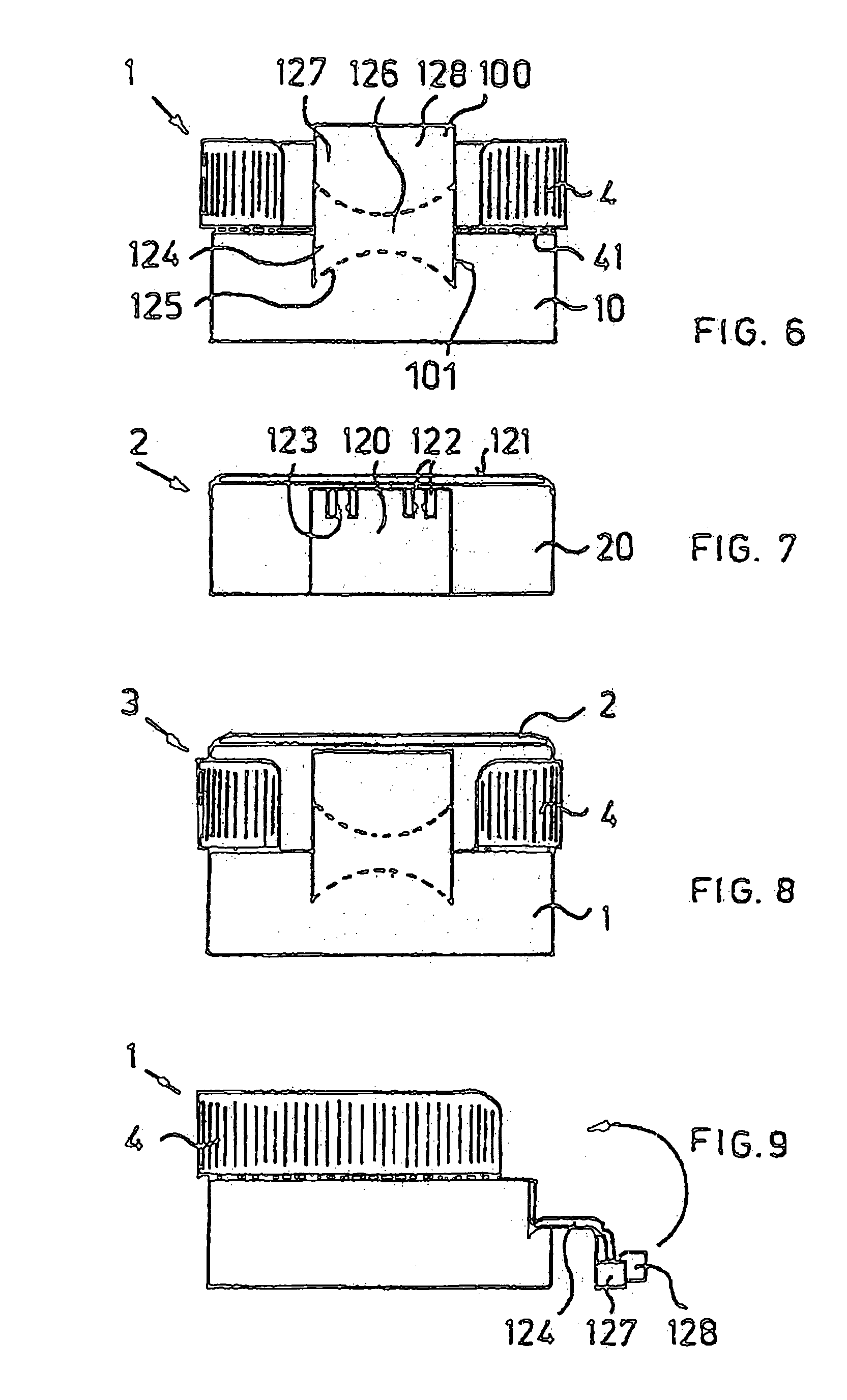
[0051]In the second embodiment in accordance with FIGS. 6 to 9, no pouring spout is shown. However, the pouring spout can be provided the same as in the previously mentioned embodiment. Accordingly, a corresponding sealing plug can also be provided in the cap 2. However, to include these elements in the drawing would clutter it too much without offering any additional information, but the elements can be provided. This in particular, because these elements play a corresponding part during assembly.

[0052]Although the two parts of the closure are individually produced and must be assembled, in comparison to known plastic closures of similar construction they are considerably cheaper because of the enormously increased productivity when manufacturing the individual parts. As previously mentioned, this productivity is the result of the selected shape and the design of the snap hinge closure from two parts.

[0053]A solution for a two-part closure 3 which is optimized with respect to produ...


PUM


Abstract

A two-part hinge closure having a lower part which has a surrounding outer wall and which can be placed on a container, and has a cap which has an outer wall and which can be joined to the lower part in a hinged manner. The lower part and the cap are separately produced and can be assembled together. In an assembled and closed state, the outer walls are situated above each other in an aligned manner, at least in the hinge area of both hinge closure parts. Both closure parts can be joined to one another by a snap hinge having at least one spring element and at least one coupling piece. When the closure is in a closed state, the at least one spring element and the at least one coupling piece are at least almost aligned with the outer wall of the closure part on which they are formed as one piece.

Description

BACKGROUND OF THE INVENTION[0001]1. Field of the Invention[0002]This invention relates to a two-part hinge closure, having a lower part, which can be placed on a container, and having a circumferential casing wall, and a cap, which can be connected with the lower part by a movable hinge and having a casing wall. Both parts are made separately of each other and can be assembled together, and in an assembled, closed state the casing walls of both hinge parts extend flush above each other.[0003]2. Description of Related Art[0004]Hinge closures made of plastic have been on the market for approximately forty years. In the simplest forms, such hinge closures made of plastic consist of a lower part and a cap, wherein the lower part and the cap are connected as one piece by a film hinge. In most cases these are not snap hinge closures. These closures came on the market in large numbers only approximately ten years later. In the meantime the various embodiments of plastic closures with snap ...

Claims


Application Information

Patent Timeline
Patent Type & Authority Patents(United States)
IPC IPC(8): B65D47/08
CPCB65D47/0861B65D2101/0023B65D2401/15
Inventor DUBACH, WERNER FRITZ
Owner TERXO
Why Eureka
Try Eureka