Shock absorbing vehicle wheel chock

a technology of shock absorption and vehicle, which is applied in the direction of brake systems, transportation and packaging, transportation items, etc., can solve the problems of substantial damage to vehicles, sudden impact or jolt of railcars, etc., and achieves the effects of reducing financial losses, high strength, and economical production

Inactive Publication Date: 2005-02-08
TITAN IND SERVICES
View PDF4 Cites 62 Cited by
  • Summary
  • Abstract
  • Description
  • Claims
  • Application Information

AI Technical Summary

Benefits of technology

The present invention is directed to an improved vehicle wheel chock assembly and which is capable of absorbing energy from a vehicle wheel due to the momentum of the vehicle when the transporting vehicle or railcar is subjected to a substantial jolt or impact. The wheel chock of the present invention is also adapted to be used with a relative large and / or heavy vehicle wheel and substantially eliminates the problem of the vehicle wheels jumping over the chocks and / or breaking the chocks and thus significantly reduces the financial loss due to damaged vehicles. The chock assembly of the invention is also adapted to be molded of a liquid thermoset plastics material which provides high strength and for economical production. In addition, the chock assembly of the invention substantially eliminates the time and cost of repairing or replacing broken wheel chocks.

Problems solved by technology

One of the problems encountered with the use of wheel chocks as disclosed in the above patents results when the wheel chocks are used with wheels of a large and / or heavy vehicle, and the railcar is subjected to a sudden impact or jolt.
If the force of the impact or jolt is sufficiently high, the momentum of the vehicle being transported causes the vehicle wheels to jump over their corresponding wheel chocks and / or break the chocks, sometimes resulting in the vehicle hitting one or more adjacent vehicles and causing substantial damage to the vehicles.

Method used


Image

  • Shock absorbing vehicle wheel chock
  • Shock absorbing vehicle wheel chock
  • Shock absorbing vehicle wheel chock

Examples


Embodiment Construction

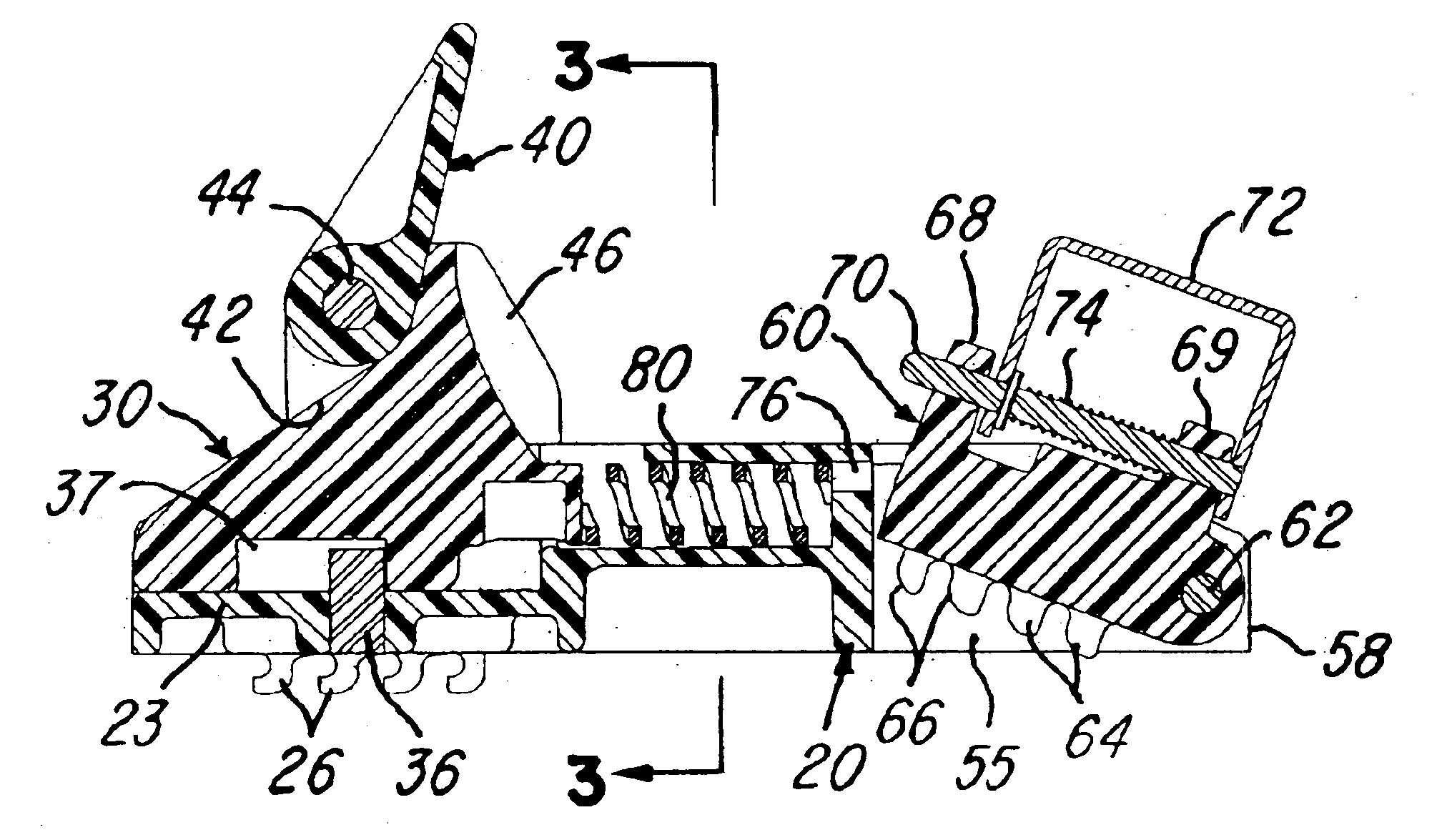
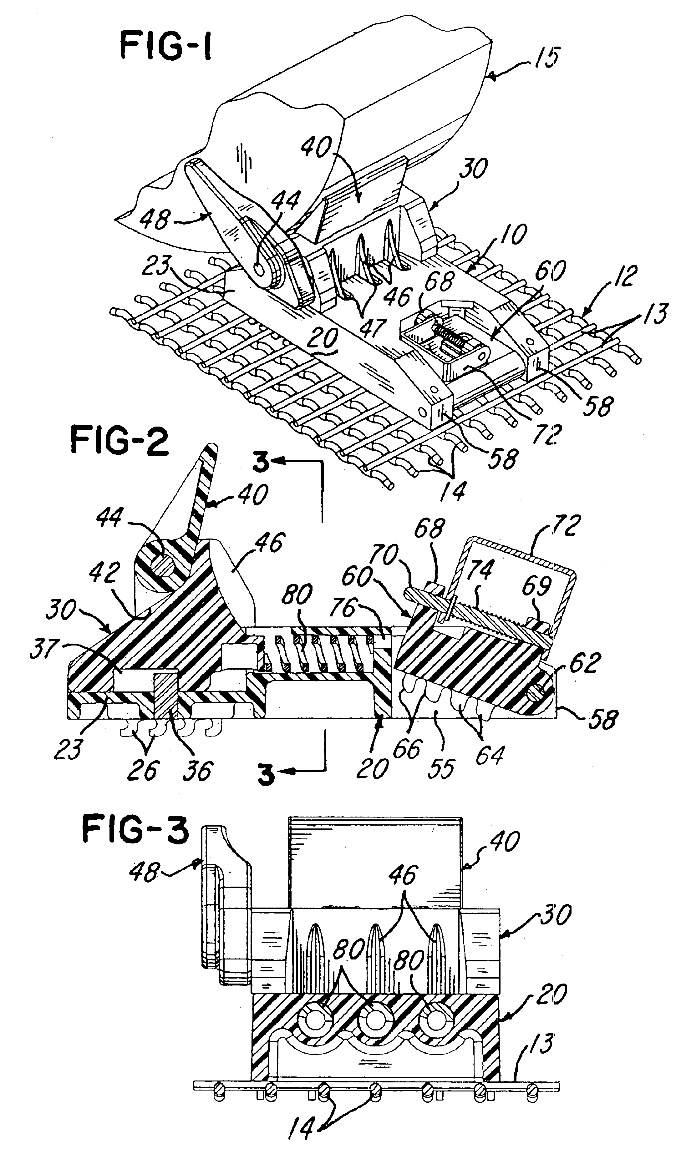
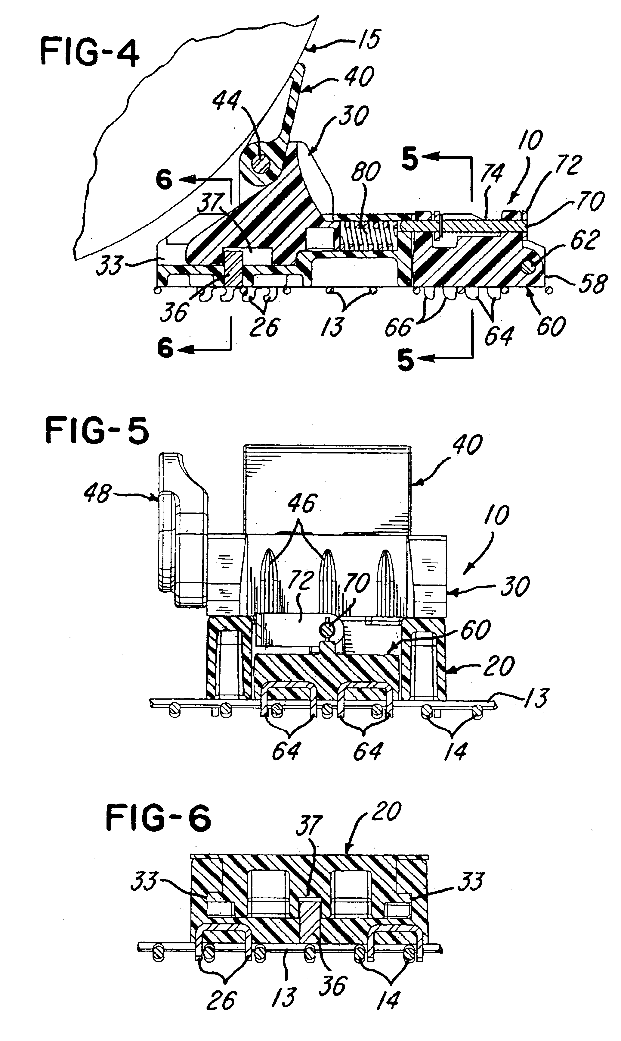
FIG. 1 illustrates a wheel chock assembly 10 constructed in accordance with the invention and shown installed on a wire grid 12 having parallel spaced steel wires 13 crossing and welded to parallel spaced steel wires 14. The chock assembly 10 is positioned adjacent the tire of a relatively large diameter wheel 15 as might be used, for example, on a pickup truck or a sport utility vehicle. As disclosed in above U.S. Pat. No. 5,302,063, the wire grid 12 is commonly attached to the bed or floor of a railcar. The chock assembly 10 may be attached at any desired location on the wire grid, depending on the location of the vehicle wheels.

The chock assembly 10 includes a body or base member 20 which is molded of a liquid thermoset plastics material primarily composed of a plural component liquid monomer mixture which can be molded by a reaction injection molding (RIM) process. An example of such a product is produced by Metton America Corporation and sold under the trademark METTON. The bas...


PUM


Abstract

A horizontally extending body or base member includes a forward portion and a rearward portion and has downwardly projecting teeth for engaging a wire grid mounted on a bed or floor. The forward portion of the base member supports a wheel engaging head member for relative horizontal movement between extended and retracted positions, and compression springs bias the head member to its extended position. A lock member is supported by the rearward portion of the base member for pivotal movement between released and locked positions and also has downwardly projecting teeth for engaging the wire grid. The head member carries a wheel engaging extension member for pivotal movement between retracted and extended positions. A side paddle member is also carried by the head member to resist lateral movement of the wheel, and preferably all of the members are each molded of a liquid thermoset plastics material.

Description

BACKGROUND OF THE INVENTIONThis invention relates to wheel chocking devices or assemblies used to secure automobiles, trucks and other vehicles to the bed or floor of a transportation vehicle such as a railroad car or “railcar”. For example, a commonly used wheel chock or device is disclosed in U.S. Pat. No. 5,302,063 and U.S. Pat. No. 5,312,213 and functions to confine or hold the vehicle being transported in place on the bed or floor to prevent damage to the vehicle and / or an adjacent vehicle and / or the railcar by shifting of the vehicle in response to forces encountered by the railcar or other transportation system. As disclosed in the above patents, the wheel chock attaches to a crossing wire mesh or wire grid which is secured to the floor or bed of the railcar.One of the problems encountered with the use of wheel chocks as disclosed in the above patents results when the wheel chocks are used with wheels of a large and / or heavy vehicle, and the railcar is subjected to a sudden i...

Claims


Application Information

Patent Timeline
Patent Type & Authority Patents(United States)
IPC IPC(8): B60P3/077B60P3/06B60T3/00
CPCB60T3/00B60P3/077
Inventor GASTER, IVAN
Owner TITAN IND SERVICES
Why Eureka
Try Eureka