Cube wire-grid polarizing beam splitter

a polarizing beam and cube wire technology, applied in the field of cube or prism wiregrid polarizing beam splitter, can solve the problems of increased back focal length of the display, increased thickness of the display, increased cost of projection lenses, etc., and achieves less expensive projection lenses, enhanced performance or contrast, and short back focal length

Inactive Publication Date: 2007-12-27
MOXTEK INC
View PDF99 Cites 72 Cited by
  • Summary
  • Abstract
  • Description
  • Claims
  • Application Information

AI Technical Summary

Benefits of technology

[0007]It has been recognized that it would be advantageous to develop a rear projection display system with a shorter back focal length, that is thinner, and/or that has less costly projection lenses. In addition, it has been recognized that it would be advantageous to develop a cube wi

Problems solved by technology

One drawback of using a wire-grid polarizing beam splitter in a rear projection display can be an increase in back focal length of the display, an increase in the thickness of the display, and/or more costly projection lenses.
It is an ongoing challenge to develop rear projecti

Method used


Image

  • Cube wire-grid polarizing beam splitter
  • Cube wire-grid polarizing beam splitter
  • Cube wire-grid polarizing beam splitter

Examples


example 1

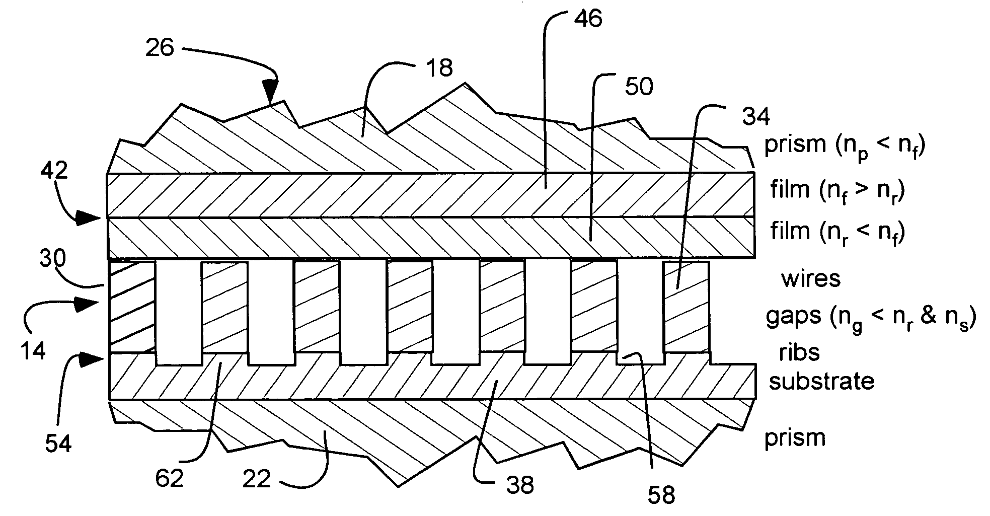
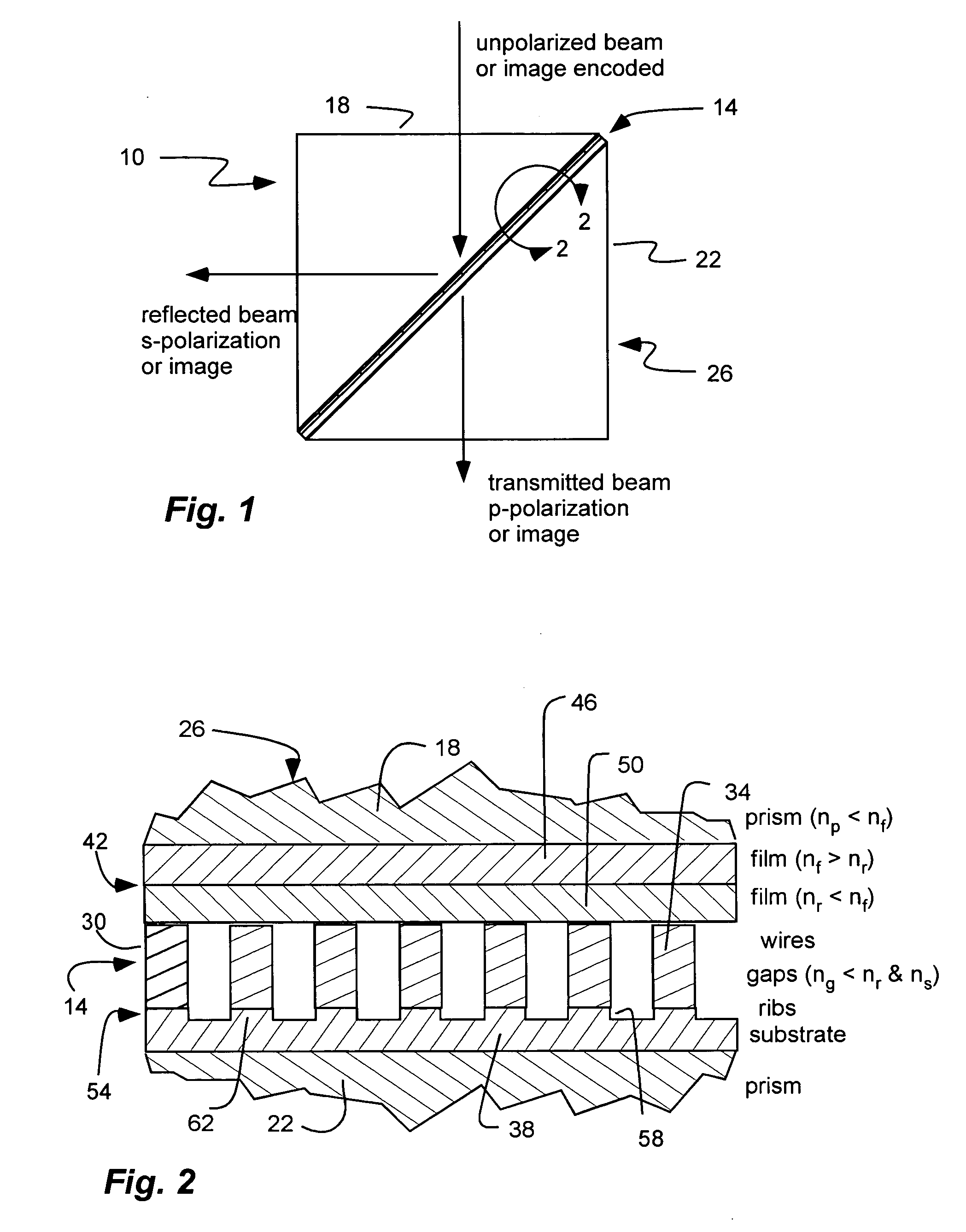
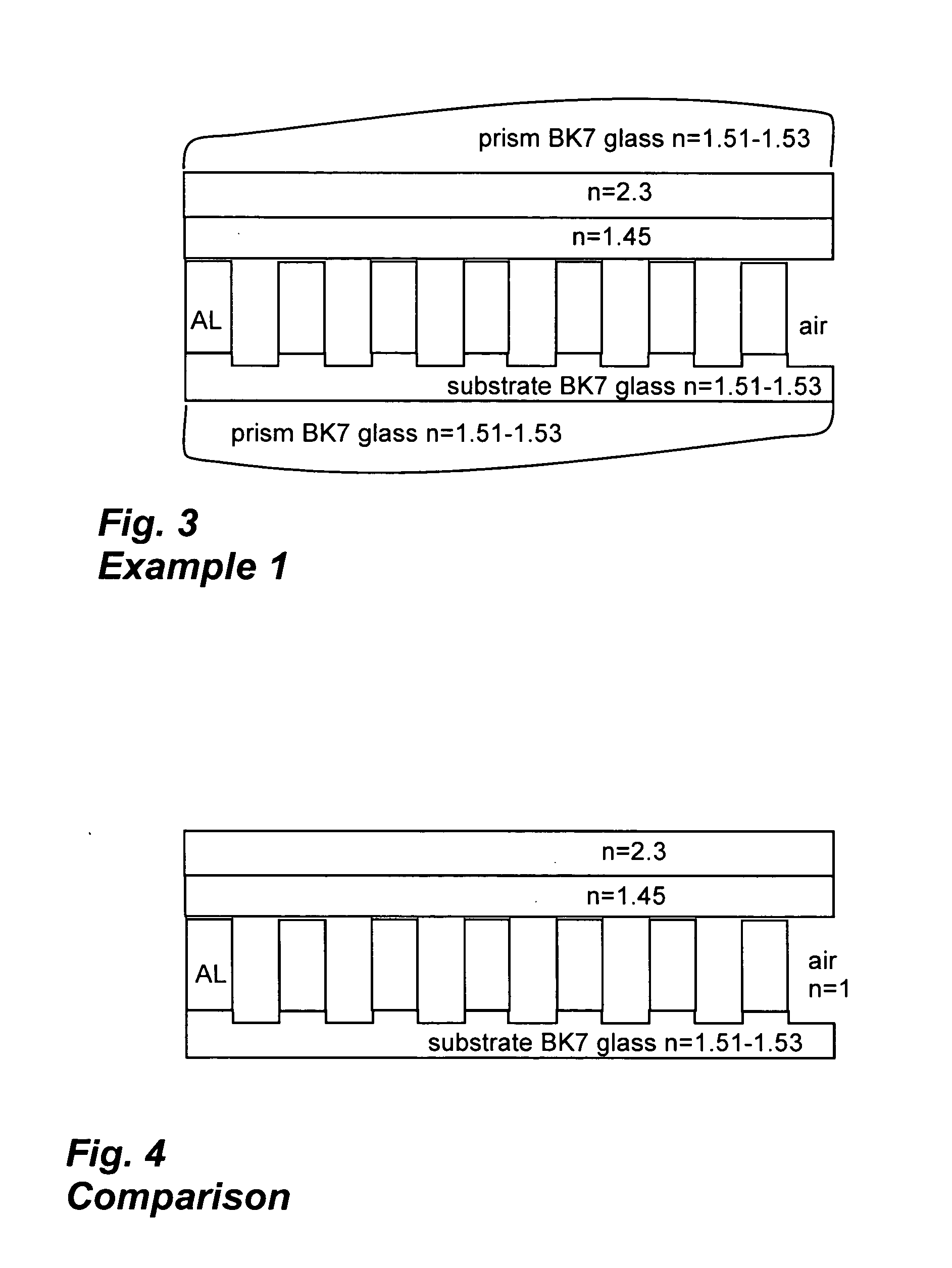
[0045]Referring to FIG. 3, a first non-limiting example of a cube wire-grid polarizer is shown. The prisms are BK7 glass (refractive index n=1.51-1.53). The substrate also is BK7 glass. The plate wire-grid polarizer includes aluminum (AL) wires and air gaps (refractive index of 1). The pitch or period of the wires is 120 nm. The rear film layer adjacent to or closer to the wires is silicon dioxide with a refractive index of n=1.45. The forward film layer adjacent to or closer to the prism is titanium dioxide with a refractive index of n=2.3.

[0046]The plate wire-grid polarizer was made by a lithography process to form the wires on the substrate. The substrate was etched between the wires to form troughs between the wires, and ribs between the troughs upon which the wires were disposed. The rear film layer was deposited over the wires, and the front film layer was deposited over the rear film layer.

[0047]By way of comparison, FIG. 4 shows a similar plate wire-grid polarizer without th...

example 2

[0051]Referring to FIG. 6, a second non-limiting example of a cube wire-grid polarizer is shown. The prisms are BK7 glass (refractive index n=1.51-1.53). The substrate also is BK7 glass. The plate wire-grid polarizer includes aluminum (AL) wires. The pitch of the wires is 120 nm. The rear film layer adjacent to or closer to the wires is spin-on glass with a refractive index of n=1.17. In addition, the material of the rear film layer fills the gaps between the wires. The front film layer adjacent to or closer to the prism is titanium dioxide with a refractive index of n=2.25.

[0052]The plate wire-grid polarizer was made by a lithography process to form the wires on the substrate. The substrate was etched between the wires to form troughs between the wires, and ribs between the troughs upon which the wires were disposed. The rear film layer was deposited over the wires, and the front film layer was deposited over the rear film layer.

[0053]The calculated performance of the cube wire-gri...


PUM


Abstract

A cube wire-grid polarizing beam splitter includes a pair of prisms secured together to form a cube. An array of parallel conductive wires is disposed between the pair of prisms. A pair of continuous film layers is disposed on one side of the wires between the wires and one of the pair of prisms with an intermediate film layer adjacent the prism having a refractive index greater than both i) a refractive index of a rear film layer adjacent the plate wire grid polarizer, and ii) a refractive index of an adjacent prism. A layer of ribs is disposed on another side of the wires between the wires and another of the pair of prisms, the ribs being aligned with and supporting the array of parallel conductive wires.

Description

RELATED APPLICATIONS[0001]This is related to U.S. patent application Ser. No. ______, filed Jun. 26, 2006, entitled “Projection Display with Cube Wire-Grid Polarizing Beam Splitter” as attorney docket no. 00546-22521; which is herein incorporated by reference.BACKGROUND[0002]1. Field of the Invention[0003]The present invention relates generally to a cube or prism wire-grid polarizer or polarizing beam splitter.[0004]2. Related Art[0005]Visible light wire-grid polarizers and wire-grid polarizing beam splitters have been developed and successfully incorporated into rear projection monitors or televisions. Such rear projection displays can use a spatial light modulator, such as a liquid crystal on silicon (LCOS) panel, to encode image information onto a polarized light beam. The wire-grid polarizer or beam splitter can be used to produce the polarized light, and / or to separate the encoded image information from the beam produced by the spatial light modulator. For example, see U.S. Pat...

Claims


Application Information

Patent Timeline
IPC IPC(8): G02B5/30
CPCG02B5/3058G02B5/1809
Inventor WANG, BINGARDNER, ERICPERKINS, RAYMOND
Owner MOXTEK INC
Why Eureka
Try Eureka