
Stereoscopic display apparatus

a display device and stereoscopic technology, applied in the field of stereoscopic display devices, can solve the problems of high cost, high cost, and high cost of batteries, and achieve the effect of reducing light loss and shortening back focal length

Inactive Publication Date: 2013-07-04
DELTA ELECTRONICS INC
View PDF2 Cites 2 Cited by
  • Summary
  • Abstract
  • Description
  • Claims
  • Application Information

AI Technical Summary

Benefits of technology

The patent text states that the invention requires no quarter wave plate on the top of the spatial light modulator, which reduces light loss and improves efficiency.

Problems solved by technology

The disadvantage of active shutter glasses is that they are heavy and expensive, and require battery replacement.
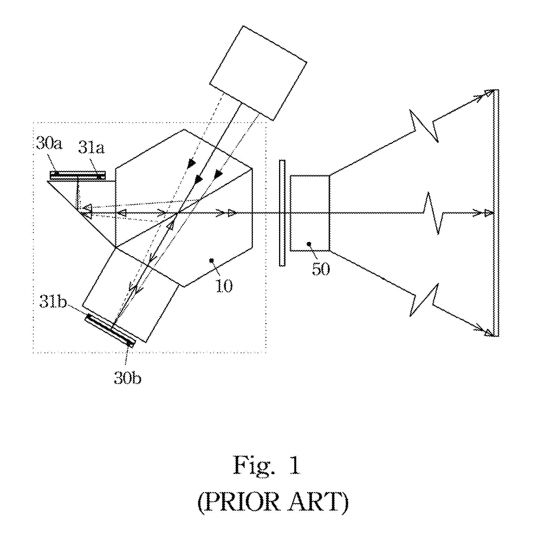
1. The polarization beam splitter (PBS) 10 is used for both separating and combining S and P polarizations for two spatial light modulators. For example, each light modulator may be a digital micro-mirror device (DMD) 30a or 30b , the incident light path is different to its reflected exit light path. The two light paths have two different incident angles. A special polarization beam splitter must be made to meet the requirements of two different incident angles because the splitting of polarizations is very angle sensitive;
2. A quarter wave plates 31a and 31b must be used on top of the spatial light modulator. When light comes and goes from the spatial light modulator, it passes this quarter wave plate twice and changes its polarization state. Again, the quarter wave plate is very angle sensitive. Light loss is unavoidable especially when come and go with two different incident angles;
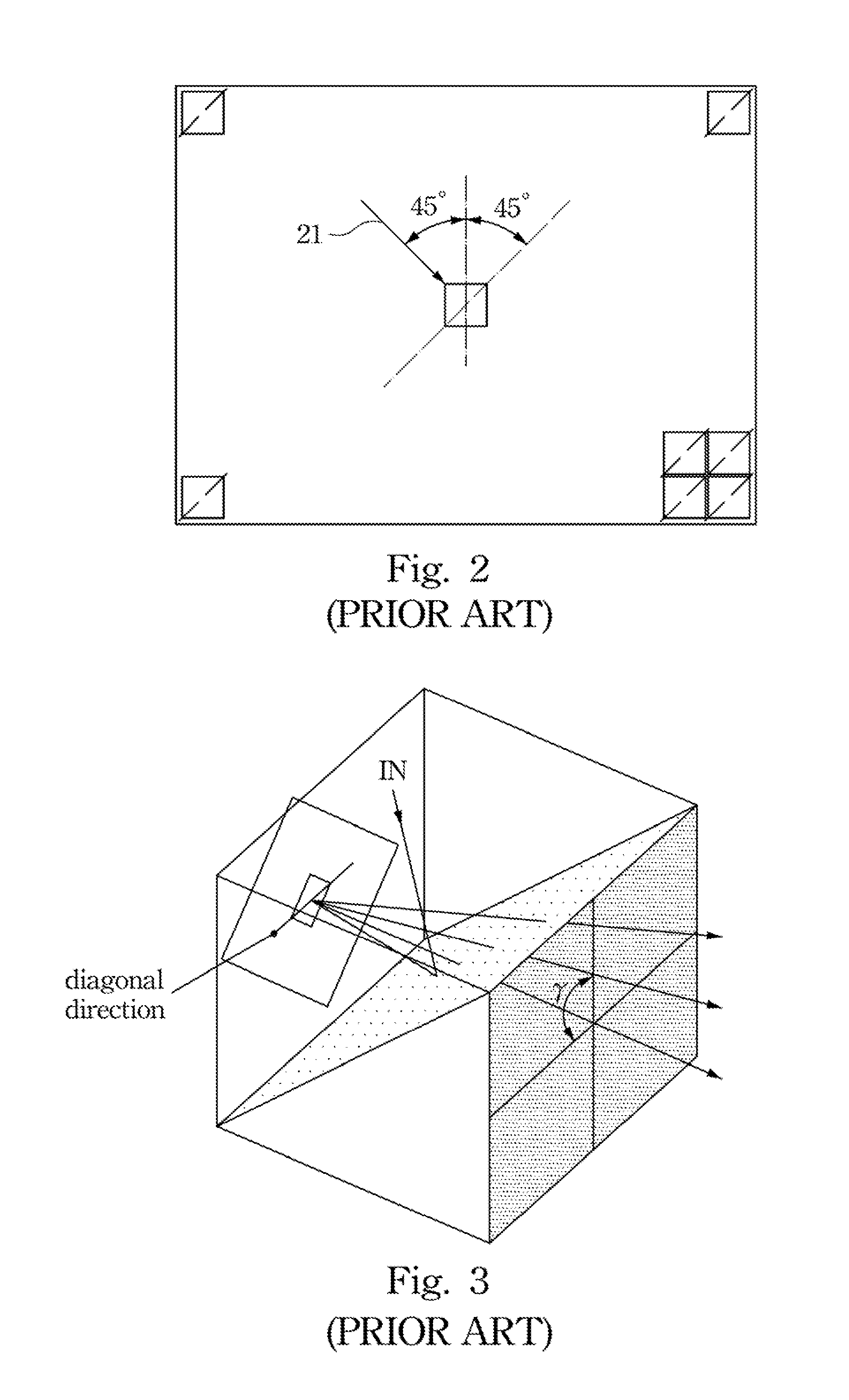
3. As shown in FIG. 2, the incident light 21 for DMD must come from its one diagonal direction. As shown in FIGS. 3 and 4, if two DMD 30a , 30b are disposed on two sides of the PBS cube 10, either two incident light paths from two different diagonal directions, or two kinds of DMD panels with pivots at two diagonal directions, must be used. If these two choices cannot be made, another extra fold must be added in one of the light paths of the DMD panels, as shown in FIG. 1. The Bigger PBS cube and longer back focal length for the projection lens 50 are the drawbacks it will introduce.
In view of the foregoing, there exist problems and disadvantages in the current 3D stereoscopic display techniques that await further improvement.
However, those skilled in the art sought vainly for a solution.

Method used


Image

  • Stereoscopic display apparatus
  • Stereoscopic display apparatus
  • Stereoscopic display apparatus

Examples


Embodiment Construction

[0034]In the following detailed description, for purposes of explanation, numerous specific details are set forth in order to attain a thorough understanding of the disclosed embodiments. It will be apparent, however, that one or more embodiments may be practiced without these specific details. In other instances, well-known structures and devices are schematically shown in order to simplify the drawing.

[0035]As used in the description herein and throughout the claims that follow, the meaning of “a”, “an”, and “the” includes reference to the plural unless the context clearly dictates otherwise. Also, as used in the description herein and throughout the claims that follow, the terms “comprise or comprising”, “include or including”, “have or having”, “contain or containing” and the like are to be understood to be open-ended, i.e., to mean including but not limited to. As used in the description herein and throughout the claims that follow, the meaning of “in” includes “in” and “on” un...


PUM


Abstract

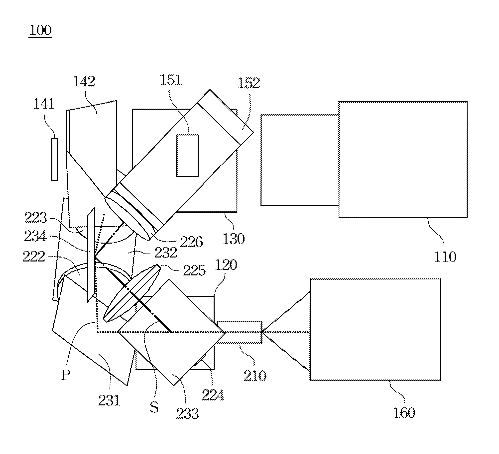
A stereoscopic display apparatus includes a projection lens, a light source, a first and a second polarized beam splitters, a first and a second optical guiding system. The light source can radiate non-polarized light. The first polarized beam splitter divides the non-polarized light into P-polarized light and S-polarized light. The first optical guiding system guides the P-polarized light to the second polarized beam splitter, and the second optical guiding system guides the S-polarized light to the second polarized beam splitter. The second polarized beam splitter combines and transmits the P-polarized light and S-polarized light to the projection lens.

Description

RELATED APPLICATIONS[0001]This application claims priority to Taiwan Application Serial Number 100149421, filed Dec. 29, 2011, which is herein incorporated by reference.BACKGROUND[0002]1. Technical Field[0003]The present disclosure relates to display devices, and more particularly, stereoscopic display apparatus.[0004]2. Description of Related Art[0005]Providing vivid images to the consumers has long been the goal of display manufacturers and researchers. Among various advanced techniques, the application of three-dimensional (3D) stereoscopy is one of the most sought after fields.[0006]From the technical aspect, 3D imaging is achieved by using the parallax due to the different views from the eyes of a viewer. Generally, 3D stereoscopic techniques may be categorized into glasses-aided stereoscopy and glass-free, naked-eye stereoscopy. For 3D stereoscopy that requires glasses, there are two types of glasses commonly used to view 3D images; that is, active shutter glasses and passive ...

Claims


Application Information

Patent Timeline
Patent Type & Authority Applications(United States)
IPC IPC(8): G02B27/26G02B30/25
CPCG02B27/283G02B27/26G02B30/25
Inventor HUANG, JUNE-JEI
Owner DELTA ELECTRONICS INC
Learn More