Zoom lens system with vibration reduction

Active Publication Date: 2006-04-06
NIKON CORP
View PDF2 Cites 29 Cited by
  • Summary
  • Abstract
  • Description
  • Claims
  • Application Information

AI Technical Summary

Benefits of technology

[0062] In the zoom lens system with a vibration reduction according to the present invention, in order to secure the effect of the invention, it is preferable to set the upper limit of conditional expression (1) to 7.0 and the lower limit to 3.8.
[0063] In the zoom lens system with a vibration reduction according to the present invention, the following conditional expression (2) is preferably satisfied:1.70<Bfw / fw<3.00  (2) where fw denotes the focal length of the zoom lens system in the wide-angle end state, and Bfw denotes the back focal length in the wide-angle end state.
[0064] Conditional expression (2) defines an appropriate range of the back focal length suitable for an interchangeable lens type single-lens-reflex digital camera. When the ratio Bfw / fw is equal to or exceeds the upper limit of conditional expression (2), the back focal length becomes too long, so that the total lens length becomes large. On the other hand, when the ratio Bfw / fw is equal to or falls below the lower limit of conditional expression (2), the back focal length becomes short, so that the rear portion of the zoom lens system interferes the mirror of the single-lens-reflex camera.
[0065] In the zoom lens system with a vibration reduction according to the present invention, in order to secure the effect of the present invention, it is preferable to set the upper limit of conditional expression (2) to 2.50 and the lower limit to 1.85.
[0066] In the zoom lens system with a vibration reduction according to the present invention, the following conditional expressions (3) and (4) are preferably satisfied:1.6<f3 / fw<4.5  (3)−2.3<f3R / f3F<−1.2  (4) where f3 denotes the focal length of the third lens group, f3F denotes the focal length of the front lens group and f3R denotes the focal length of the rear lens group.
[0067] Conditional expression (3) defines an appropriate range of the focal length of the third lens group suitable for mitigating deterioration in optical performance caused by fabrication error. When the ratio f3 / fw is equal to or exceeds the upper limit of conditional expression (3), the total lens length and lens diameter of the zoom lens system becomes excessively large, so that it becomes difficult to be in practical use. On the other hand, when the ratio f3 / fw is equal to or falls below the lower limit of conditional expression (3), the back focal length becomes short and deterioration in optical performance caused by decentering between the front lens group of the third lens group and the fourth lens group resulting from fabrication error becomes large.

Problems solved by technology

Accordingly, when these zoom lens systems are used for a single-lens-reflex camera necessary to have a long back focal length or, in particular, for a single-lens-reflex digital camera using a solid-state imaging device having a smaller image size than a 35 mm film format (36 mm by 24 mm) necessary to have a back focal length similar to a single-lens-reflex camera of a 35 mm film format, it causes problems that a sufficiently wide angle of view cannot be obtained, or the rear part of the zoom lens system interferes a mirror of a single-lens-reflex camera.

Method used


Image

  • Zoom lens system with vibration reduction
  • Zoom lens system with vibration reduction
  • Zoom lens system with vibration reduction

Examples


example 1

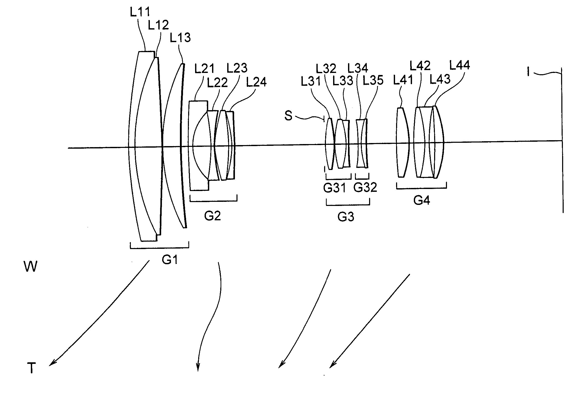
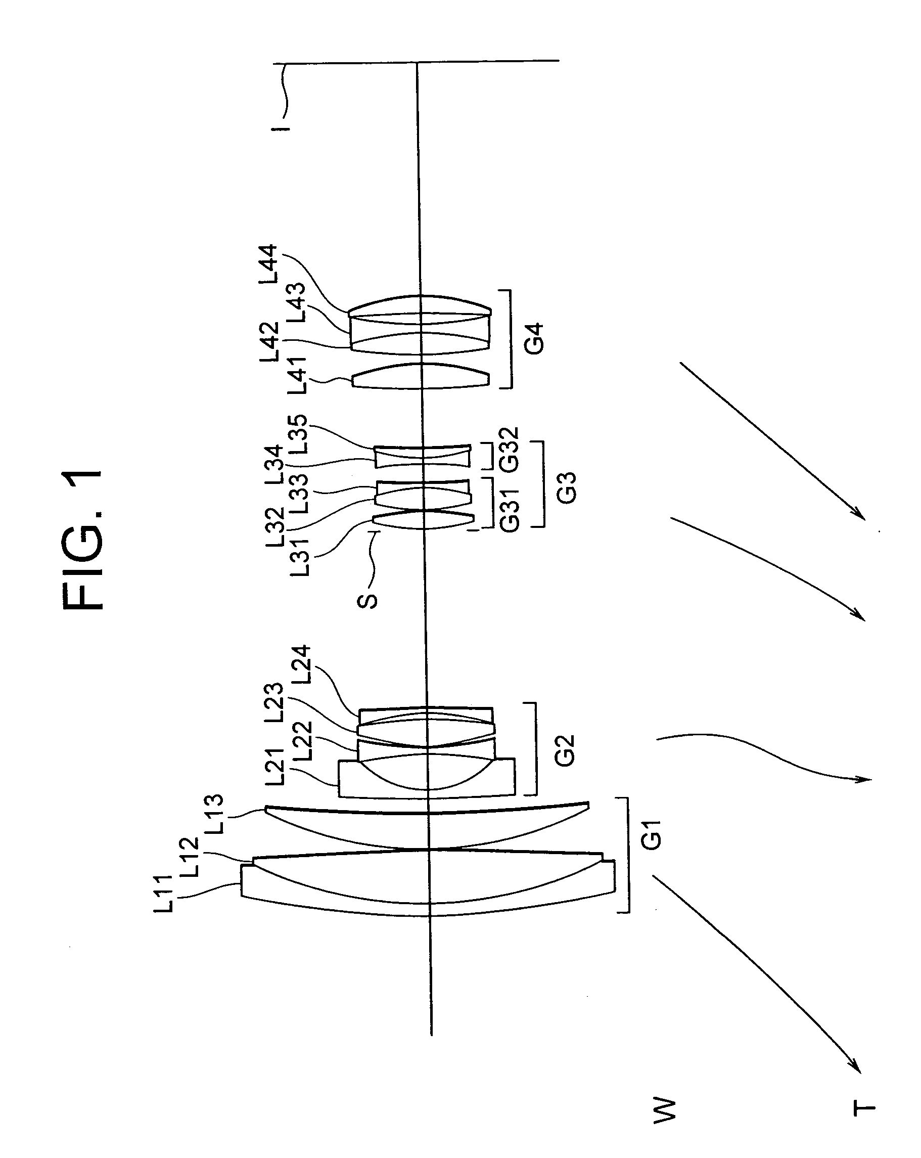
[0130]FIG. 1 is a diagram showing the lens configuration of a zoom lens system with a vibration reduction according to Example 1 of the present invention.

[0131] The zoom lens system with a vibration reduction according to Example 1 is composed of, in order from an object, a first lens group G1 having positive refractive power, a second lens group G2 having negative refractive power, an aperture stop S, a third lens group G3 having positive refractive power, and a fourth lens group G4 having positive refractive power.

[0132] In the zoom lens system with a vibration reduction according to Example 1, when a state of lens group positions varies from a wide-angle end state to a telephoto end state, the first lens group G1, the third lens group G3, and the fourth lens group G4 move to the object and the second lens group G2 moves such that a distance between the first lens group G1 and the second lens group G2 increases, a distance between the second lens group G2 and the third lens grou...

example 2

[0157]FIG. 5 is a diagram showing the lens configuration of a zoom lens system with a vibration reduction according to Example 2 of the present invention.

[0158] The zoom lens system with a vibration reduction according to Example 2 is composed of, in order from an object, a first lens group G1 having positive refractive power, a second lens group G2 having negative refractive power, an aperture stop S, a third lens group G3 having positive refractive power, and a fourth lens group G4 having positive refractive power.

[0159] In the zoom lens system with a vibration reduction according to Example 2, when a state of lens group positions varies from a wide-angle end state to a telephoto end state, the first lens group G1, the third lens group G3, and the fourth lens group G4 move to the object and the second lens group G2 moves such that a distance between the first lens group G1 and the second lens group G2 increases, a distance between the second lens group G2 and the third lens grou...

example 3

[0174]FIG. 9 is a diagram showing the lens configuration of a zoom lens system with a vibration reduction according to Example 3 of the present invention.

[0175] The zoom lens system with a vibration reduction according to Example 3 is composed of, in order from an object, a first lens group G1 having positive refractive power, a second lens group G2 having negative refractive power, an aperture stop S, a third lens group G3 having positive refractive power, and a fourth lens group G4 having positive refractive power.

[0176] In the zoom lens system with a vibration reduction according to Example 3, when a state of lens group positions varies from a wide-angle end state to a telephoto end state, the first lens group G1, the third lens group G3, and the fourth lens group G4 move to the object and the second lens group G2 moves such that a distance between the first lens group G1 and the second lens group G2 increases, a distance between the second lens group G2 and the third lens grou...


PUM


Abstract

To provide a zoom lens system with a vibration reduction having a long back focal length suitable for a digital SLR camera, a high zoom ratio, and a wide angle of view of 70° or more. The system includes, in order from the object, a first positive lens group, a second negative lens group, a third positive lens group, and a fourth positive lens group. Upon zooming from wide-angle end state to telephoto end state, a distance between the first and second lens groups increases, a distance between the second and third lens groups decreases, and a distance between the third and fourth lens groups varies. The third lens group is composed of a positive front lens group and a negative rear lens group. Image plane correction upon camera shake can be performed by shifting only the rear lens group substantially perpendicularly to the optical axis. Given conditions are satisfied.

Description

[0001] The disclosures of the following priority applications are herein incorporated by reference: [0002] Japanese Patent Application No. 2004-290346 filed on Oct. 1, 2004 and [0003] Japanese Patent Application No. 2005-102731 filed on Mar. 31, 2005. BACKGROUND OF THE INVENTION [0004] 1. Field of the Invention [0005] The present invention relates to a zoom lens system with a vibration reduction, in particular, to a zoom lens system having a long back focal length, a high zoom ratio, and a large angle of view in the wide-angle end state suitable for a single-lens-reflex camera. [0006] 2. Related Background Art [0007] Various kinds of zoom lens systems with a vibration reduction have been proposed in Japanese Patent Application Laid-Open Nos. 2001-166208, 2002-6217, 2003-140048, and 2003-295060. [0008] However, in each zoom lens system disclosed in Japanese Patent Application Laid-Open Nos. 2001-166208, 2002-6217, 2003-140048, and 2003-295060, the back focal length in the wide-angle ...

Claims


Application Information

Patent Timeline
IPC IPC(8): G02B15/14
CPCG02B15/173G02B27/646G02B15/144113
Inventor SHIBAYAMA, ATSUSHISUZUKI, TAKESHIITO, TOMOKI
Owner NIKON CORP
Why Eureka
Try Eureka