Camera support base

a camera and support technology, applied in the field of removable supports, can solve the problems of inability to serve, heavy support, and damage to the camera, especially the lens,

Inactive Publication Date: 2008-06-24
SOULVIE JOHN
View PDF20 Cites 55 Cited by
  • Summary
  • Abstract
  • Description
  • Claims
  • Application Information

AI Technical Summary

Benefits of technology

[0008]The camera support base of the instant invention is designed to meet the need for a stable, lightweight, compact, economical fixture or support that can be removably affixed with ease to a photographic camera in order to safely support the camera when it is set down out-of-hand beyond the control of the photographer.
[0009]The camera support base of the invention is preferably manufactured from aluminum or engineered plastics, such as Acrylonitrile-Butadiene-Styrofoam (ABS) plastic; polyoxymethylene plastics, such as Delrin™ (a product of E. I. du Pont de Nemours) or Celcon™ (a product of the Celanese Corporation of America); polycarbonates, such as Lexan™ (a product of du Pont); and polyethylene terephthalate. Depending on the expected service duty, such plastics as polyvinyl chloride (PVC) and polyethylene can also be used. Using any of these plastic resins, the design of the camera support base of the invention lends itself to economical production by injection molding in a variety of models.
[0013]To broaden the applicability and compatibility of the camera support base of the invention with as many models of cameras as possible, the top portion of the base contains a number of slots and apertures, some threaded, to accommodate connecting as many models as possible to the base. Some slots run with the direction of the length of the top portion, while in other models the slots run with the width of the top portion. The slots are wide enough to accommodate a threaded bolt.

Problems solved by technology

Often, damage to the camera, particularly the lens, can result.
But these base supports are bulky, expensive, or just unable to serve the needs of a casual, momentary, camera set aside by the photographer.
However, even when the camera is attached to a tripod, the camera frequently must be laid out-of-hand during a photographic session.
Just as frequently, the camera, especially high end cameras, are usually supporting several attachments, such as flash equipment, telescopic lens and the like, that make the camera an awkward ensemble and vulnerable to accidental damage if laid aside without extra care.

Method used


Image

  • Camera support base
  • Camera support base
  • Camera support base

Examples


Embodiment Construction

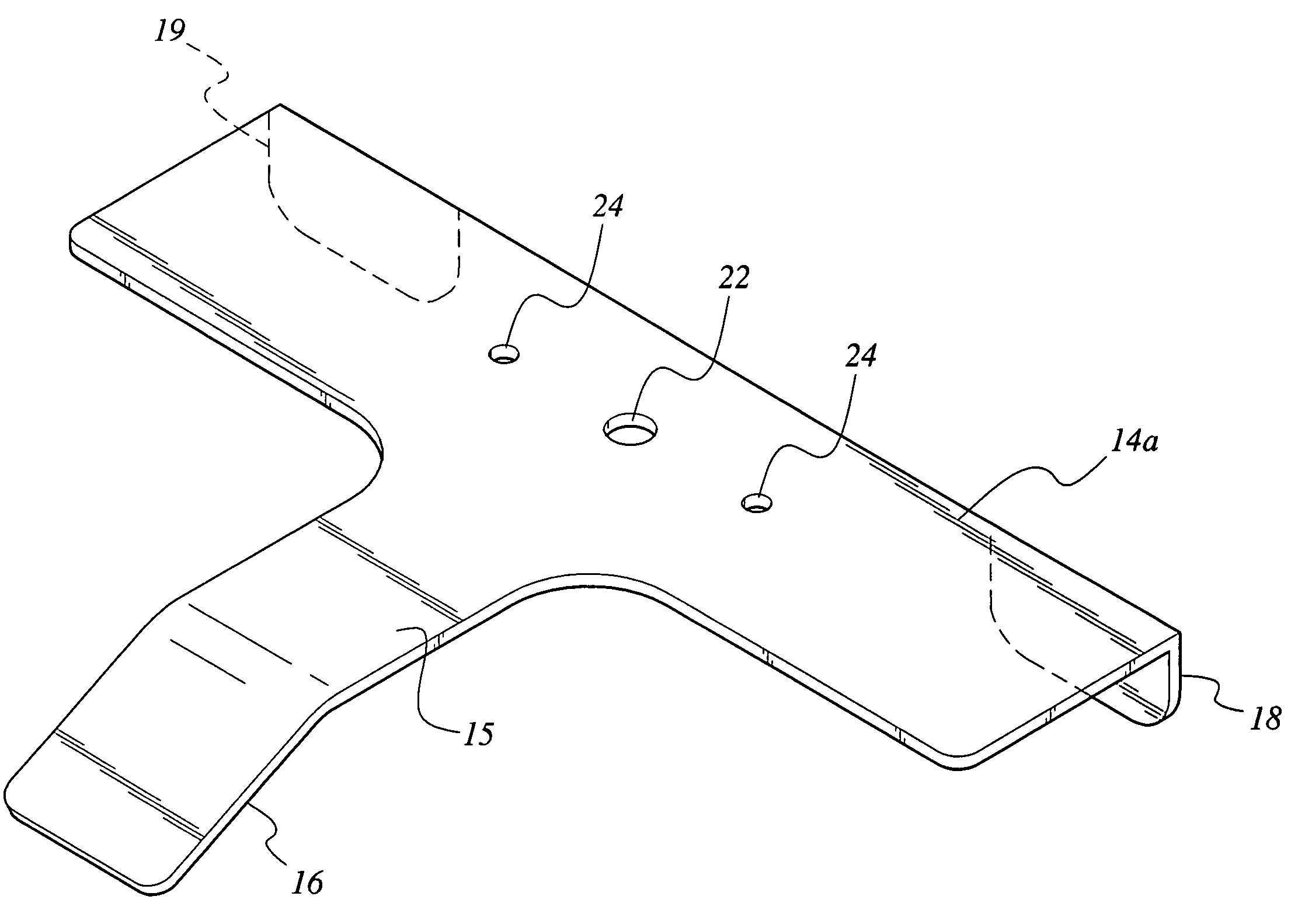
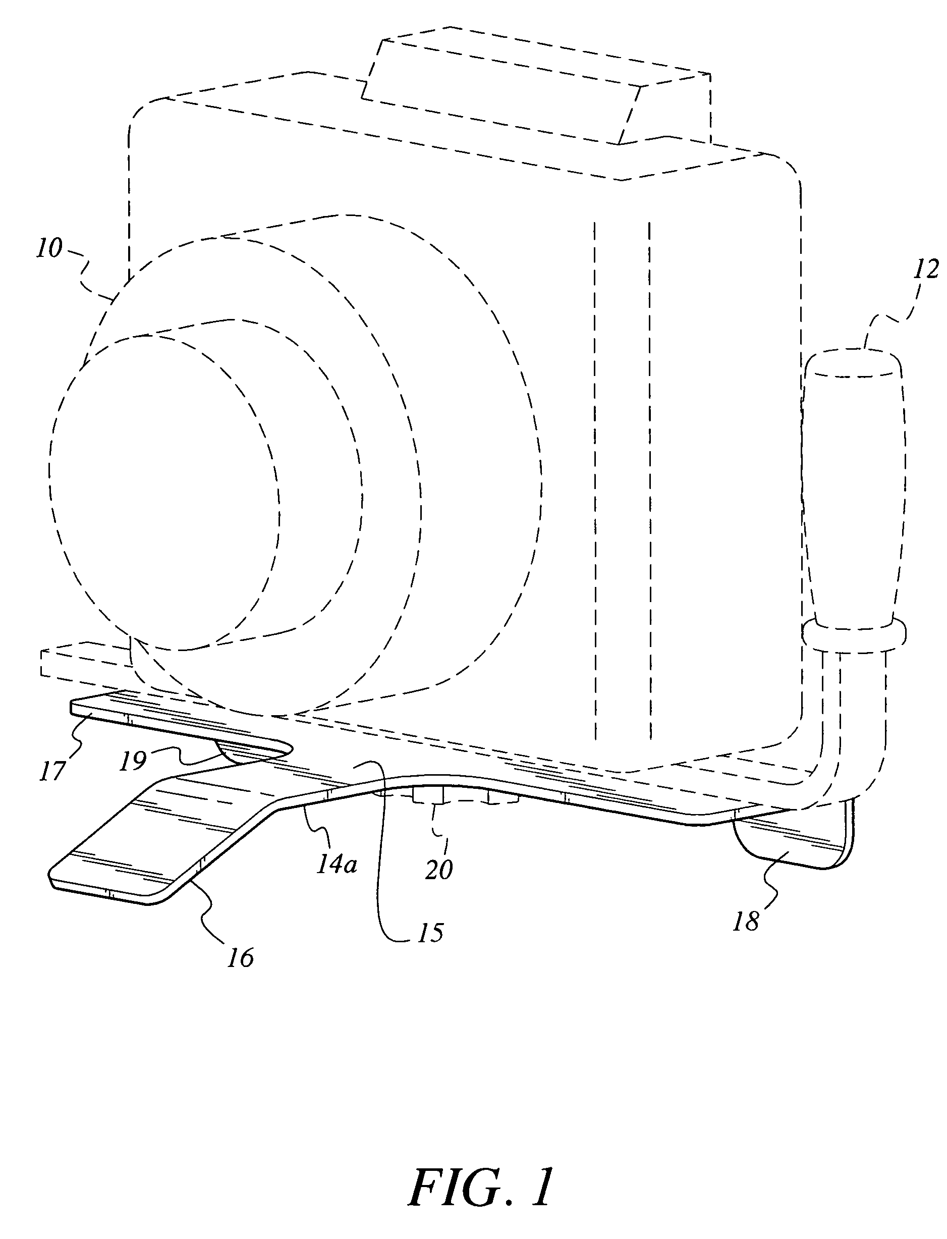
[0023]Referring to FIG. 1, a view is presented of the camera support base 14a of the invention supporting a camera 10 and a camera attachment 12. The base 14a is preferably shaped as a “T” with at least three legs to support the base. Two supports or legs 18, 19 are at opposing ends of the cross member 17 or plate of the T, and a third support or leg 16 is at the end of a shaft 15 extending from the cross member 17 of the T, forming a continuous part thereof. The cross member 17 and the shaft 15 intersect in the same plane. Preferably, third leg 16 is formed by biasing the distal section of the shaft 15 of the T at about a 45° angle. The camera 10 is attached to the camera support base 14a by threaded bolt 20 through an aperture in the camera support base 14a.

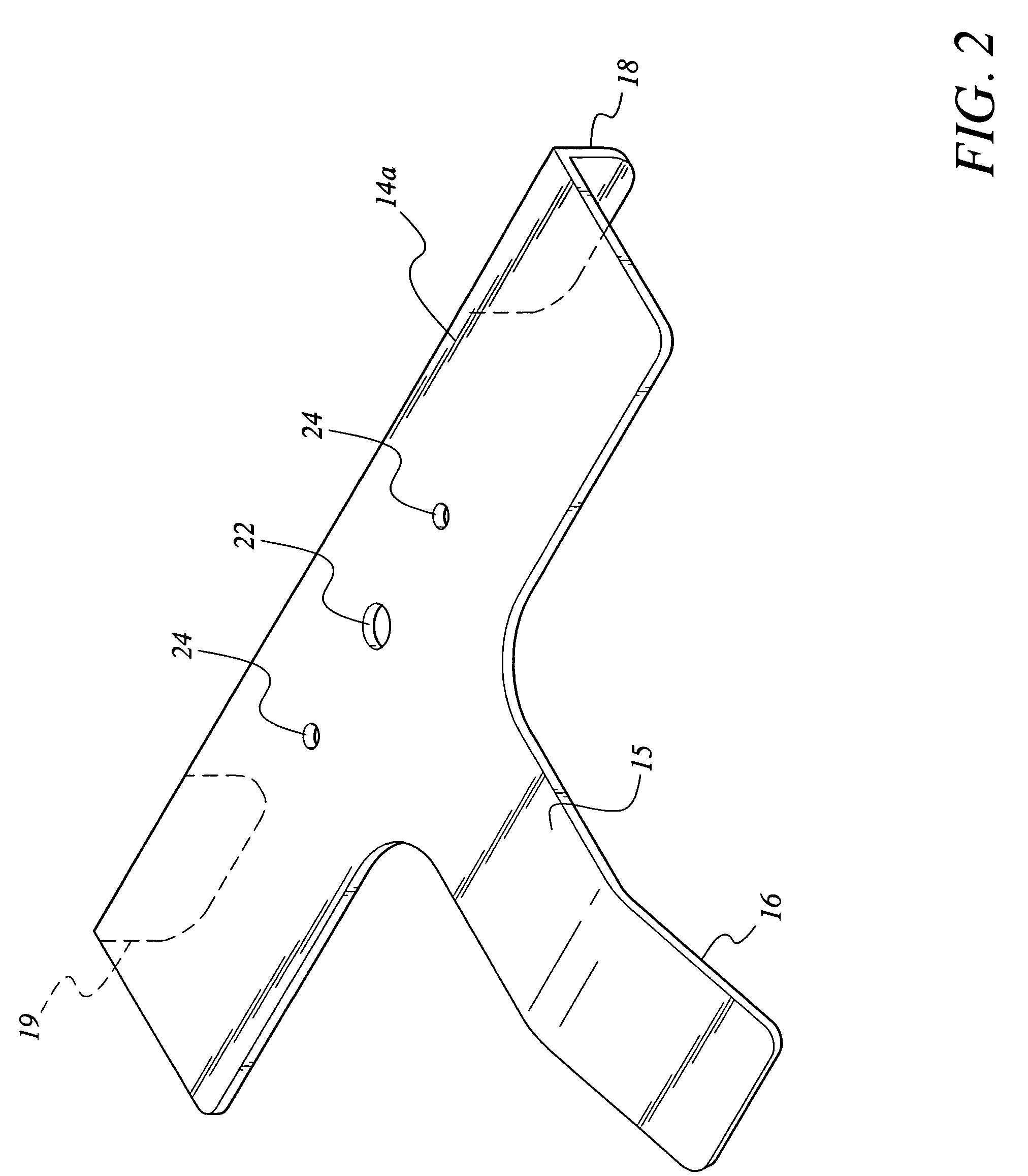
[0024]Referring to FIG. 2, the preferred camera support base 14a of the present invention is illustrated as a T-shaped body having apertures that may be unthreaded apertures 24 or threaded apertures 22 defined through the mids...


PUM


Abstract

The camera support base of the invention is designed to meet the need for a stable, lightweight, compact, economical fixture that can be removably affixed to a photographic camera to safely support the camera when it is set down out-of-hand. A preferred basic design of the camera support base comprises a three legged device that assumes the overall general shape of a “T”, having a flat horizontal top portion or plate bisected by a flat perpendicular vertical portion in the same plane. The widths of the top portion and the vertical portion can be the same or different with a width wide enough at the juncture of the two portions to assure contact with the bottom part of a camera sufficient to support the camera and secure it to the base.

Description

BACKGROUND OF THE INVENTION[0001]1. Field of the Invention[0002]The present invention relates to a removable base to securely attach to and support a photographic camera that prevents the camera from tipping or falling with consequential damage when not in use.[0003]2. Description of the Related Art[0004]Candid camera enthusiasts, both hobbyists and professionals, have long felt the need for a means to support and protect their camera when it has been put aside for a moment to attend to other equipment or subject matters. When out of the hands of the photographer, the shape of most cameras produces an uneven distribution in weight, which enhances the tendency for the camera to tip over or roll over, even when laid on flat surfaces. Often, damage to the camera, particularly the lens, can result. In the world of camera equipment there are support bases of many types, especially the ubiquitous tripod, that can adjust to different heights and safely secure the camera in most instances. ...

Claims


Application Information

Patent Timeline
Patent Type & Authority Patents(United States)
IPC IPC(8): G03B17/00H04N5/225
CPCG03B17/00
Inventor SOULVIE, JOHN
Owner SOULVIE JOHN
Why Eureka
Try Eureka