Method of manufacturing heat pipe having sintered powder wick

a technology of heat pipe and powder wick, which is applied in the direction of lighting and heating apparatus, lining repair, furniture, etc., can solve the problems of reducing the capillary force needed to draw condensed liquid, difficult to control the pore size distribution of the wick formed, and unfavorable construction of uniform wick, etc., to achieve high manufacturing capacity, increase heat pipe heat transfer performance, and economical production

Inactive Publication Date: 2006-09-07
HON HAI PRECISION IND CO LTD
View PDF7 Cites 62 Cited by
  • Summary
  • Abstract
  • Description
  • Claims
  • Application Information

AI Technical Summary

Benefits of technology

[0009] The advantage of the casting procedure in relation to other methods, e.g. the conventional sintering process, is that the powders necessary to construct the sintered powder wick are evenly mixed or distributed in the mixture of the slurry. Therefore, the sintered powder wick constructed from this procedure has a uniform structure in the pore size distribution over the wick formed, which is contributory to eliminating the dry-out problem and increasing the heat transfer performance of the heat pipe employing this wick. Also coupled with the procedure is the advantage of a high manufacturing capacity and an economical production.

Problems solved by technology

However, this method is unfavorable to construct a uniform wick in that it is difficult to control the pore size distribution over the wick formed.
The pore size distribution of a wick, however, has a great impact on the performance of that wick, since excessively small pore size will generate a large flow resistance to the condensed liquid to flow back and excessively large pore size will noticeably decrease the capillary force that is needed to draw the condensed liquid back.
Therefore, a wick that has an uneven pore size distribution will greatly affect its performance in conveying the condensed liquid, and sometimes will cause the heat pipe incorporating that wick to suffer dry-out problem at the evaporating section when the condensed liquid is not timely sent back to that evaporating section.

Method used


Image

  • Method of manufacturing heat pipe having sintered powder wick
  • Method of manufacturing heat pipe having sintered powder wick
  • Method of manufacturing heat pipe having sintered powder wick

Examples


Embodiment Construction

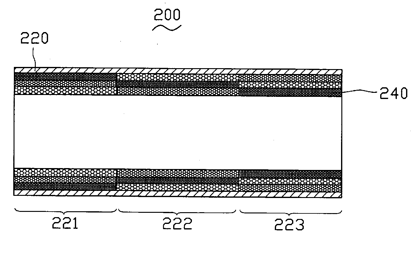
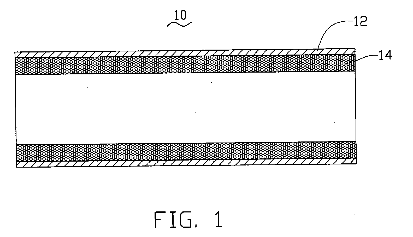
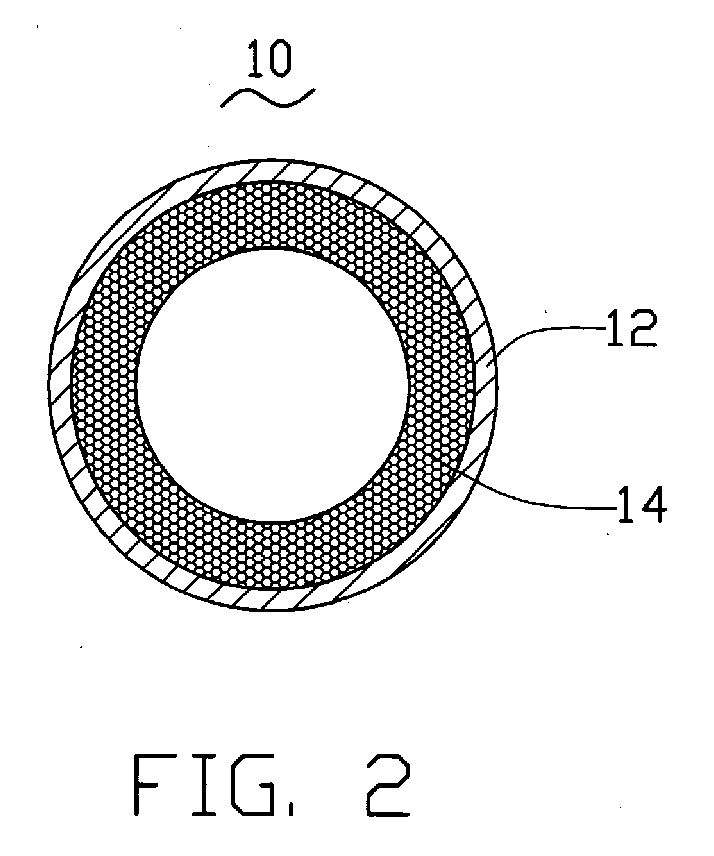
[0026]FIGS. 1-2 illustrate a sintered heat pipe 10 formed in accordance with a method of the present invention. The sintered heat pipe 10 includes a casing 12 and a sintered powder wick 14 arranged against an inner wall of the casing 12. The casing 12 is made of high thermally conductive material such as copper or aluminum. Although the casing 12 illustrated is in a round shape, it should be recognized that other shapes, such as polygon, rectangle, or triangle, may also be suitable. The wick 14 is saturated with a working fluid (not shown), which acts as a heat carrier when undergoing phase transitions between liquid state and vaporous state. The sintered powder wick 14 is a porous structure and is formed by sintering process, in which small-sized powders are sintered together under high temperatures. The heat pipe 10 is vacuumed. Although it is not shown in the drawings, it is well known by those skilled in the art that two ends of the heat pipe 10 are sealed.

[0027] In the present...


PUM

PropertyMeasurementUnit
thicknessaaaaaaaaaa
sizesaaaaaaaaaa
sizeaaaaaaaaaa

Abstract

A method is disclosed to produce a heat pipe with a sintered powder wick formed inside the heat pipe. The method employs tape-casting technology to firstly produce thin sheets of powder and then these sheets are sintered to form the wick. In the tape casting procedure, a slurry of the powders necessary to construct said wick is cast onto a moving surface to form a slurry layer and then the slurry layer is dried to form a green tape. The green tape is rolled onto a mandrel and then is inserted into a hollow casing and sintered to cause the powders in the green tape to diffusion-bond together. Thus, the sintered powder wick is constructed.

Description

DESCRIPTION [0001] 1. Field of the Invention [0002] The present invention relates generally to an apparatus for transferring or dissipating heat from heat-generating components such as electronic components, and more particularly to a method of manufacturing a sintered heat pipe. [0003] 2. Description of Related Art [0004] Heat pipes have excellent heat transfer performance due to their low thermal resistance, and therefore are an effective means for transfer or dissipation of heat from heat sources. Currently, heat pipes are widely used for removing heat from heat-generating components such as central processing units (CPUs) of computers. A heat pipe is usually a vacuum casing containing therein a working fluid, which is employed to carry, under phase transitions between liquid state and vapor state, thermal energy from one section of the heat pipe (typically referring to as the “evaporating section”) to another section thereof (typically referring to as the “condensing section”). ...

Claims


Application Information

Patent Timeline
Patent Type & Authority Applications(United States)
IPC IPC(8): F27D1/16E04B1/16B29C63/06
CPCF16L9/10F16L9/14F27D1/16
Inventor CHENG, CHING-TAIWU, JUNG-YUANHONG, CHU-WANLO, CHANG-TING
Owner HON HAI PRECISION IND CO LTD
Why Eureka
Try Eureka