
Mechanism for automatic protection switching in a router

a technology of automatic protection and router, applied in the field of routers, can solve the problems of inability to meet the requirements of a number of applications, the interface is down, and the download of files using the central controller of the router is a relatively long operation

Inactive Publication Date: 2005-12-13
RPX CLEARINGHOUSE
View PDF12 Cites 69 Cited by
  • Summary
  • Abstract
  • Description
  • Claims
  • Application Information

AI Technical Summary

Problems solved by technology

The downloading of files using the central controller of the router is a relatively lengthy operation which comprises a major portion of the time required to complete a failover from a failed line card to a replacement line card.
When the working line card fails, a central controller detects the failure of the working driver and thinks the interface is down.
Such delays are unacceptable in a number of applications, such as when a router is used to forward and maintain phone conversation connections.

Method used


Image

  • Mechanism for automatic protection switching in a router
  • Mechanism for automatic protection switching in a router
  • Mechanism for automatic protection switching in a router

Examples


Embodiment Construction

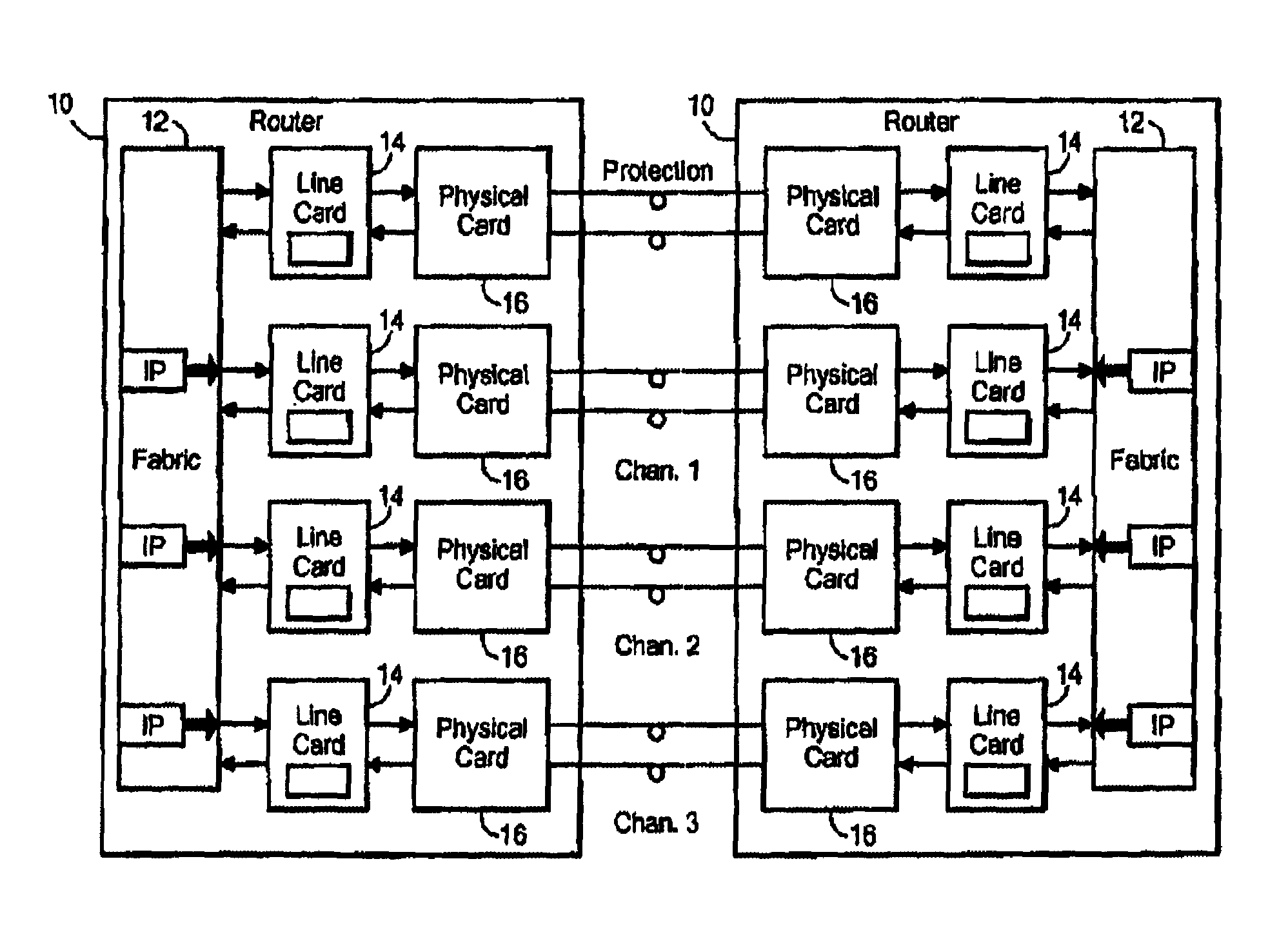
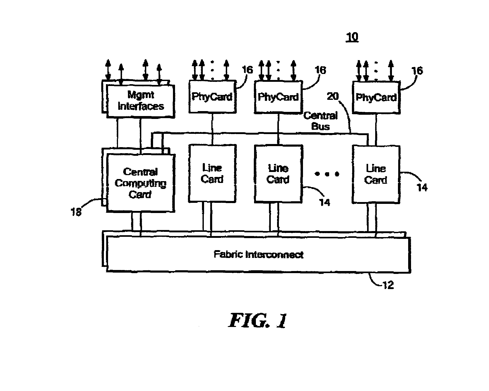
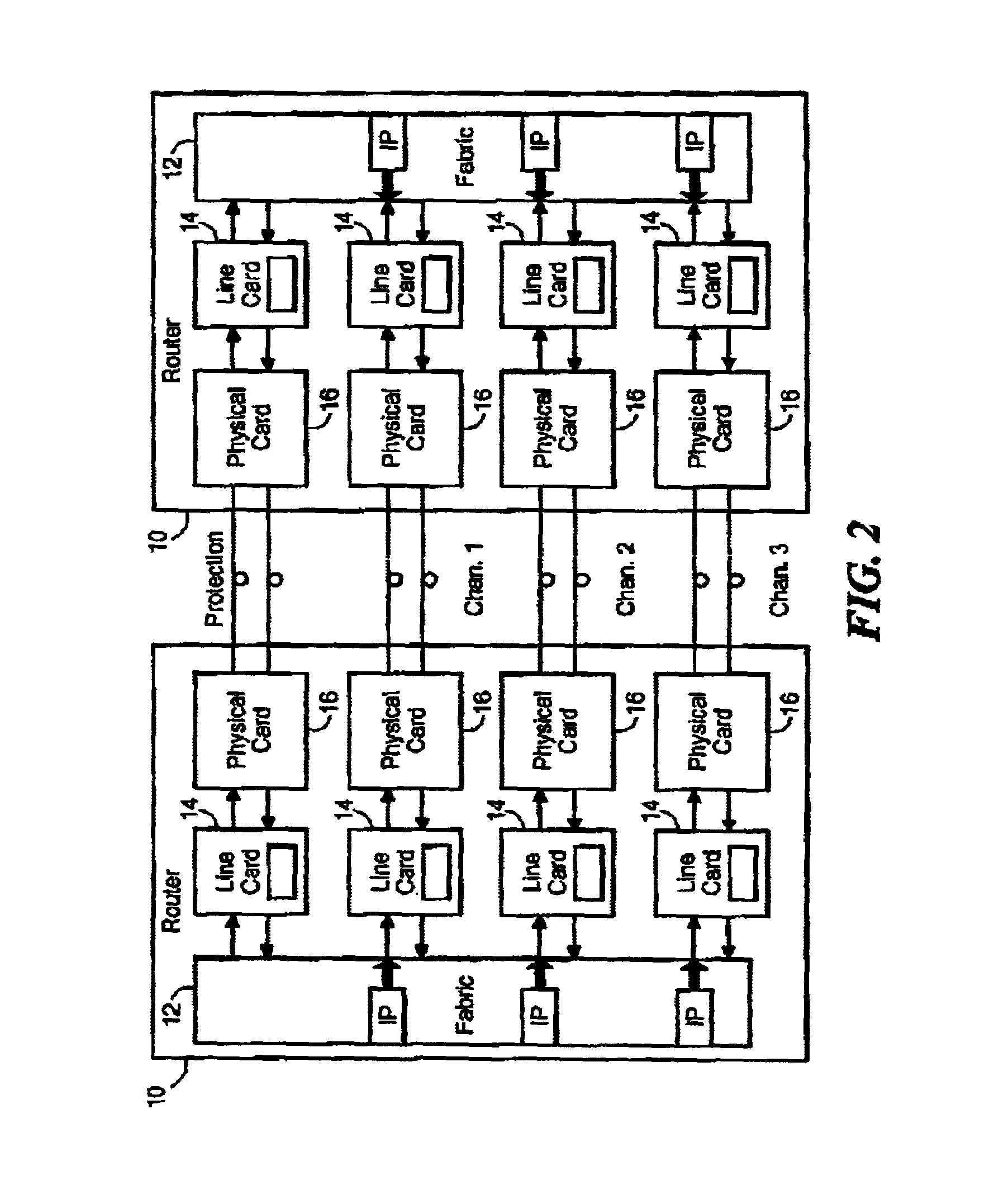
[0015]Referring now to FIG. 1, a router 10 has a communication fabric 12 through which messages received on an inbound path of one line card 14 can be forwarded to an outbound path of any line card 14 in the router in order to direct a message towards its ultimate destination. The line cards 14 are inserted in slots that connect them with the communication fabric 12. The communication fabric 12 may also be known or referred to as a switching fabric. The line cards 14 are in connection with the communication fabric 12 for receiving and sending messages through the router 10. Each line card 14 is also connected to a physical card 16 which handles communications with other routers through external connections. The physical card 16 runs a higher level routing protocol such as SONET.

[0016]The router 10 further includes a central computing engine 18. In preferred embodiments, a pair of redundant central computers 18 are employed. The central computing engine 18 is connected to the fabric ...


PUM


Abstract

In a router, externally received messages addressed to an active line card are bridged to a protection line card. Each line card in the router is programmed to respond to such externally received messages by directing them to the protection line card associated with the active line card as well as to the active line card. The protection line card is configured with inbound and outbound path tables that are the clones of the inbound and outbound path tables of its corresponding active line card. Bridging is accomplished by revising descriptors stored in a plurality of line cards to indicate an association between an active one of the line cards and its protection line card. Received messages are addressed using the revised descriptors to the active line card and also to its protection line card. Upon failure of an active line card, its physical interface can be disabled once its protection line card has clones of the inbound and outbound path tables and bridging has been set up.

Description

FIELD OF THE INVENTION[0001]The present invention is directed to routers, in particular, a method for increasing the speed of failover between an active line card and a protection line card in a router.BACKGROUND OF THE INVENTION[0002]A router typically includes a series of line cards in connection with a communication fabric. A routing table is initially downloaded to each line card along with configuration files. One of these files in particular, the dispatch table, is specifically constructed for suitability for use within a local routing switch processor in the line card. Thus, the dispatch file is an example of an interface specific table. Other files may be more global in nature and are similarly downloaded to each of the line cards. When a line card or one of the routing paths on the line card fails, a message is sent to the router's central controller which triggers the downloading of configuration files and routing table to an available working line card that will then take...

Claims


Application Information

Patent Timeline
IPC IPC(8): G01R31/08H04L12/28H04L12/56
CPCH04L45/586H04L49/557H04L49/55
Inventor ADAMSKI, DANBENSON, DAVIDJAMOUSSI, BILELLI, YUNZHOUSHANTIGRAM, JAGANNATH
Owner RPX CLEARINGHOUSE
Learn More