Retractable handle of wheeled luggage having one or two pulling rods

a technology of pulling rods and handles, which is applied in the direction of wing knobs, furniture parts, manufacturing tools, etc., can solve the problems of discomfort in hand holding of luggage, adversely affecting a degree of comfort, and prior art suffering from several

Inactive Publication Date: 2005-12-27
CHAW KHONG TECH
View PDF12 Cites 39 Cited by
  • Summary
  • Abstract
  • Description
  • Claims
  • Application Information

AI Technical Summary

Benefits of technology

[0006]It is an object of the present invention to provide a retractable handle of a wheeled luggage comprising a pulling rod including one or more sliding tubes and a support tube; and a swivel handle grip mounted on a top of the pulling rod and comprising an enclosed frame including a top recessed seat, a horizontal passage, first and second openings on a bottom of the seat, a top third opening on the seat, a bottom recess, and a bottom tunnel on the bottom recess; and a first transmission mechanism comprising a push button slidably anchored in the third opening, the push button including a spring biased first bottom post having a slanted end passed the first opening and a second bottom post having a slanted end passed the second opening, an upper sliding block disposed in the passage and including a first compartment, a second compartment having a slanted surface with the slanted end of the first bottom post disposed thereon, and a third compartment having a slanted surface with the slanted end of the second bottom post disposed thereon, a flexible connecting rod having one end fastened at the first compartment, a spring biased lower sliding block disposed in the bottom recess and including a left cavity with the other end of the connecting rod fastened therein and a bottom dent, a central sleeve extended downward from a bottom of the frame of the handle grip, the sleeve having an intermediate neck and a lower annular toothed member having a plurality of slots therearound, an upright rod slidably received in the bore of the sleeve, the upright rod having a sharp top end passed the bottom tunnel to urge against the dent, a locking member engaged with two opposite ones of the slots and a bottom of the upright rod, a spring biased upright member engaged with a bottom of the locking member, and a sheath interconnecting the sleeve and the upper sliding tube for enclosing the neck, the toothed member, the upright rod, the locking member, and the upright member; whereby pressing the push button will lower the first and the second posts to push the slanted surfaces rightwards for moving one end of the connecting rod to move to the right and the lower sliding block to move to the left so that the top end of the upright rod is pressed by the dent to cause the upright rod, the locking member, and the upright member to move down to clear the locking member from the slots of the toothed member, thereby unlocking both the handle grip and the pulling rod.

Problems solved by technology

As such, such can adversely affect a degree of comfort while holding the handle in towing luggage because the fingers are extended discomfortably.
However, the prior art suffered from several disadvantages.
For example, there is no provision of swivel mechanism on the handle grip (i.e., no rotation on a horizontal plane is provided), resulting in a discomfortable holding thereof by the hand.
Further, the handle interconnected the push button and the locking device is not devised well.

Method used


Image

  • Retractable handle of wheeled luggage having one or two pulling rods
  • Retractable handle of wheeled luggage having one or two pulling rods
  • Retractable handle of wheeled luggage having one or two pulling rods

Examples


Embodiment Construction

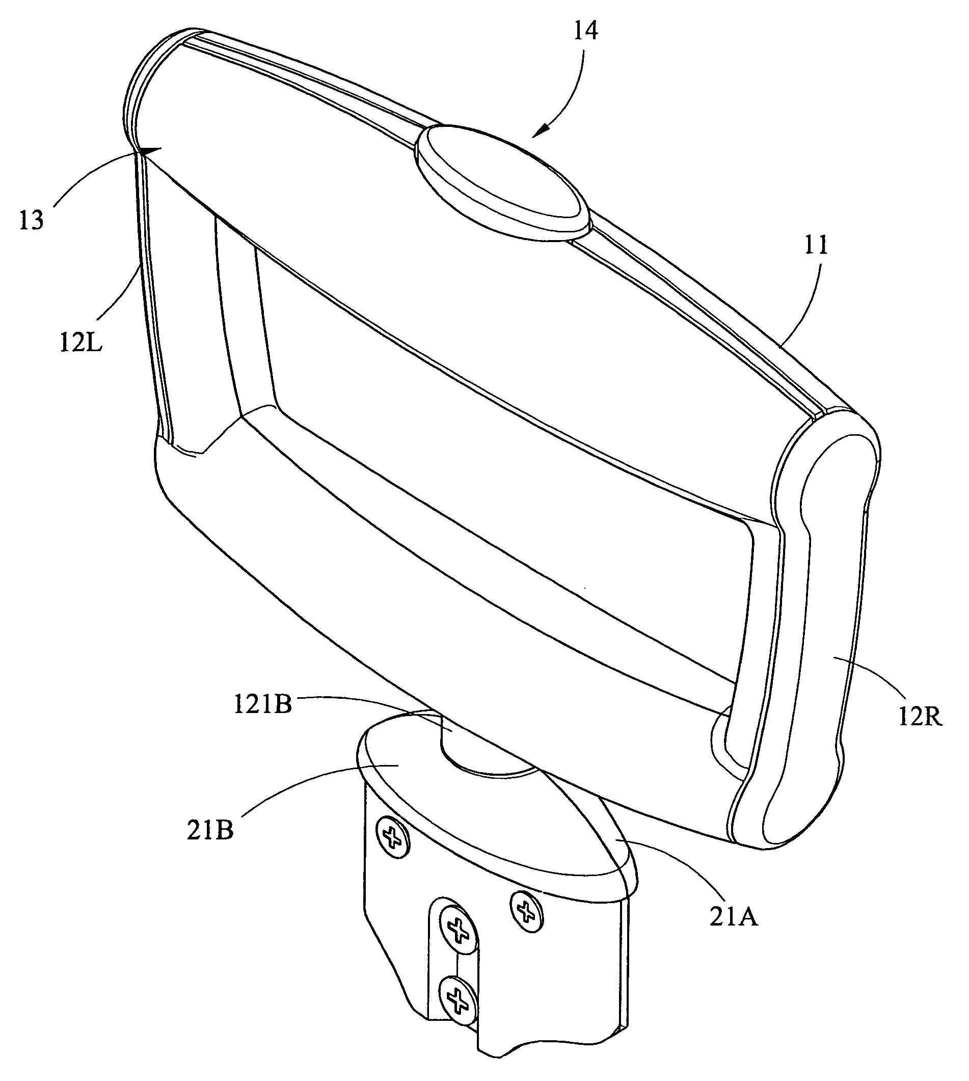
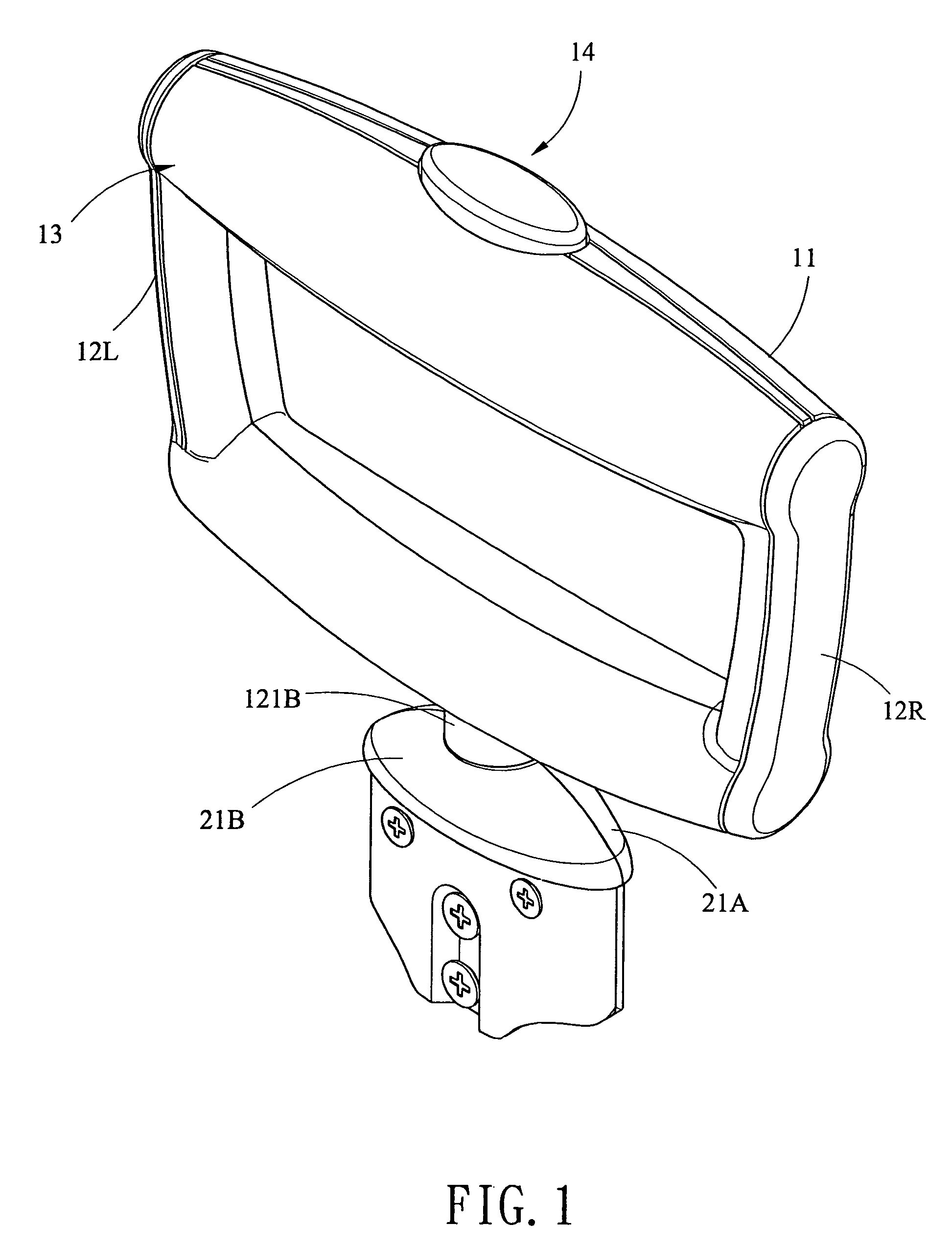
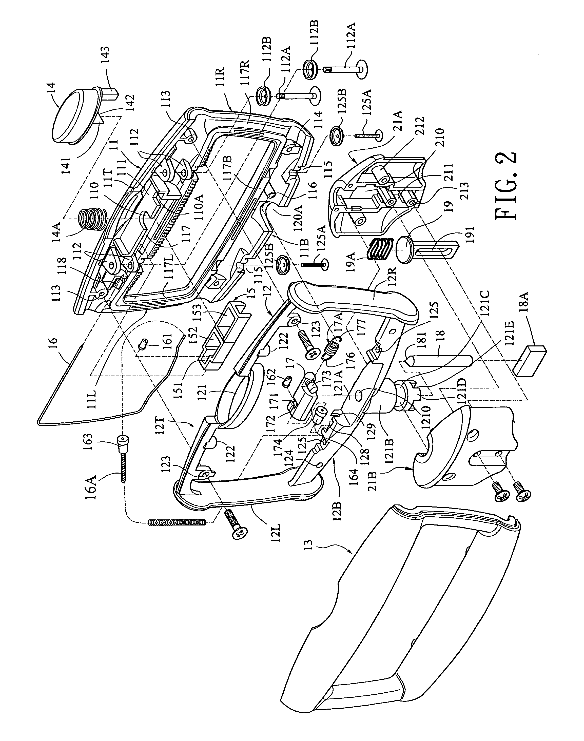
[0022]Referring to FIGS. 1 to 5, a retractable handle of wheeled luggage constructed in accordance with a first preferred embodiment of the invention is shown. A handle grip, mounted on a single pulling rod of the handle, comprises a right frame element 11, a central frame element 12, a left frame element 13, a push button 14 including a central post 141 having a slanted end at the bottom and a side post 143 having a slanted end at the bottom, the push button 14 provided on the central frame element 12, a first spring 14A put on the central post 141, an upper sliding block 15 laterally moveable in a distance along top edges of both the right and the left frame elements 11 and 13, a flexible connecting rod 16 extended from the upper sliding block 15 to the lower sliding block 17 via left portions of the right and the left frame elements 11 and 13, a lower sliding block 17 including a left cavity 171 with a second head 162 of the connecting rod 16 fastened therein, a short passage 172...


PUM


Abstract

A retractable handle of wheeled luggage is provided. For the case of single pulling rod, pressing a push button will tighten a connecting rod to move a lower sliding block to a one direction so that an upright rod is pressed to lower a locking member and an upright member to clear the locking member from a toothed member, thereby unlocking both the swivel handle grip and the pulling rod. For the case of two pulling rods, there is further provided another transmission mechanism so that pressing the push button will further unlock locking devices in the pulling rods via coupling rods.

Description

BACKGROUND OF THE INVENTION[0001]1. Field of The Invention[0002]The present invention relates to retractable handle of a wheeled luggage case and more particularly to such a handle having one or two pulling rods each having a handle grip in the shape of enclosed frame (e.g., rectangle).[0003]2. Description of Related Art[0004]Conventionally, a retractable handle of a wheeled luggage case having a single pulling rod has a shape of T (i.e., T-shaped handle grip) disclosed in U.S. Pat. No. 6,434,790. For maintaining structural strength of the handle, the single pulling rod typically has a diameter at least two times larger than that of pulling rod of the popular n-shaped handle. As such, such can adversely affect a degree of comfort while holding the handle in towing luggage because the fingers are extended discomfortably.[0005]A rectangular handle grip proposed to eliminate the above problem associated with T-shaped handle grip is disclosed in U.S. Pat. No. 6,148,477. However, the pri...

Claims


Application Information

Patent Timeline
Patent Type & Authority Patents(United States)
IPC IPC(8): A45C13/26
CPCA45C13/262A45C2013/265Y10T16/473Y10T16/455Y10T16/451A45C2013/267
Inventor KUO, CHUNG-HSIENWANG, HUI MING
Owner CHAW KHONG TECH
Why Eureka
Try Eureka