
Automatic camera tracking using beamforming

a beamforming and camera technology, applied in the field of videoconference systems, can solve the problems of inconvenient and distracting manual tracking of the camera from one speaker to the next, inability to allow the recipient of images, and limited sound detection ability of the audio detection mechanism, so as to achieve the sum amplitude of the signals received

Active Publication Date: 2005-12-27
HEWLETT PACKARD DEV CO LP
View PDF21 Cites 97 Cited by
  • Summary
  • Abstract
  • Description
  • Claims
  • Application Information

AI Technical Summary

Benefits of technology

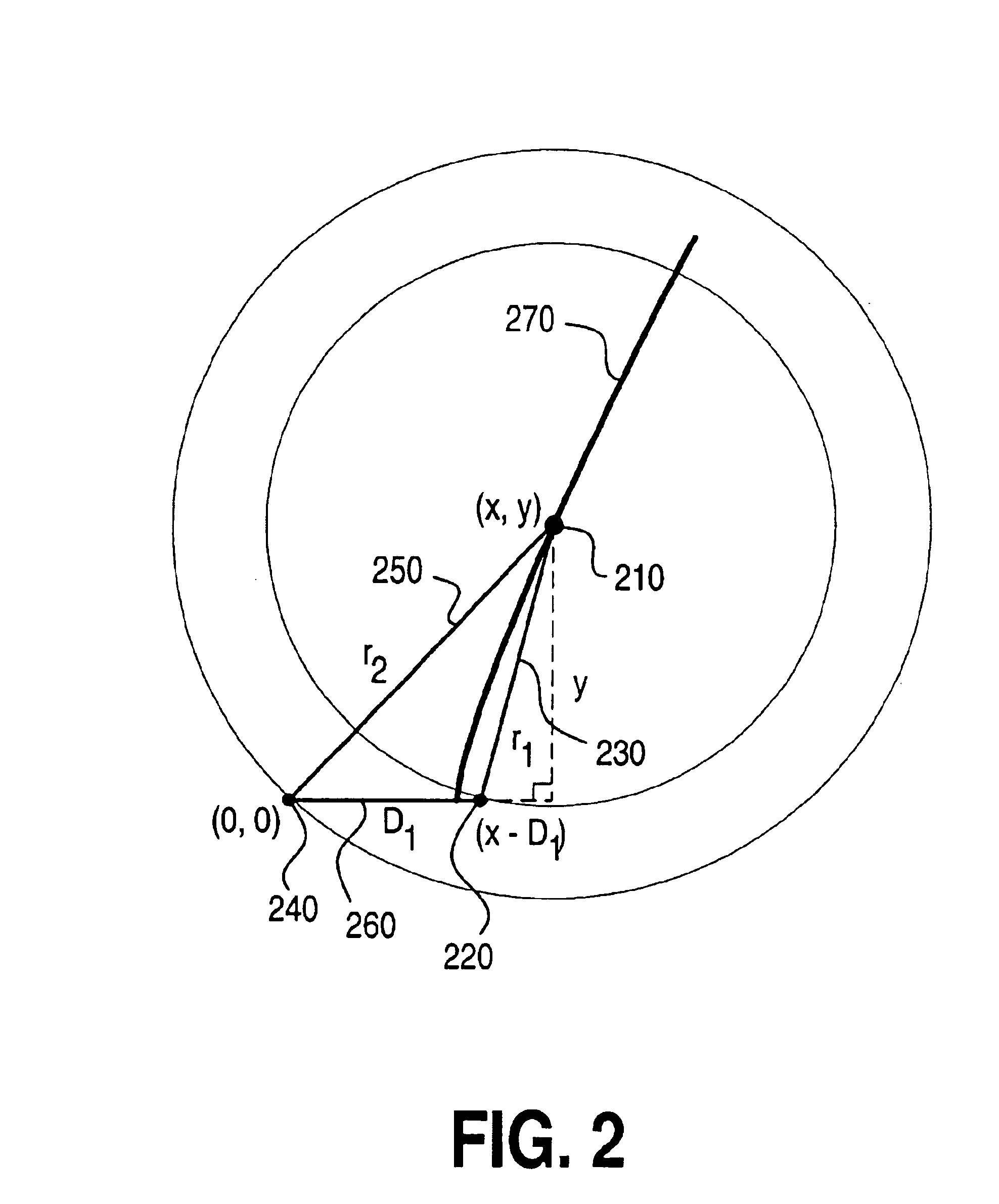
[0017]In another embodiment, the invention provides a method for identifying the location of an audio source. The method includes the steps of defining at least two points where the audio source may be located, calculating beamforming parameters for each of the at least two points in space, receiving sound by a microphone array, applying each set of the beamforming parameters to the sound received by the microphones in the array, determining which set of beamforming parameters maximize the sum amplitude of the signals received by the microphone array; and identifying one of the at least two points in space associated with the set of beamforming parameters that maximize the sum amplitude of the microphone signals.

Problems solved by technology

However, such camera shots are impersonal and do not allow the recipient of the image to pick up on nuances of the speaker's facial expressions because they lack sufficient detail.
Manually tracking the camera from one speaker to the next is inconvenient and distracting.
Because the audio detection mechanism is limited in its ability to locate sound, a special camera is used to enhance the peripheral portion of the field of view.
The system, however, requires processor intensive Fast Fourier Transform calculations to be made continuously.
The method requires a very advanced processor, an optical transducer, and is subject to many false signals (e.g., one participant whispering to a neighbor).

Method used


Image

  • Automatic camera tracking using beamforming
  • Automatic camera tracking using beamforming
  • Automatic camera tracking using beamforming

Examples


Embodiment Construction

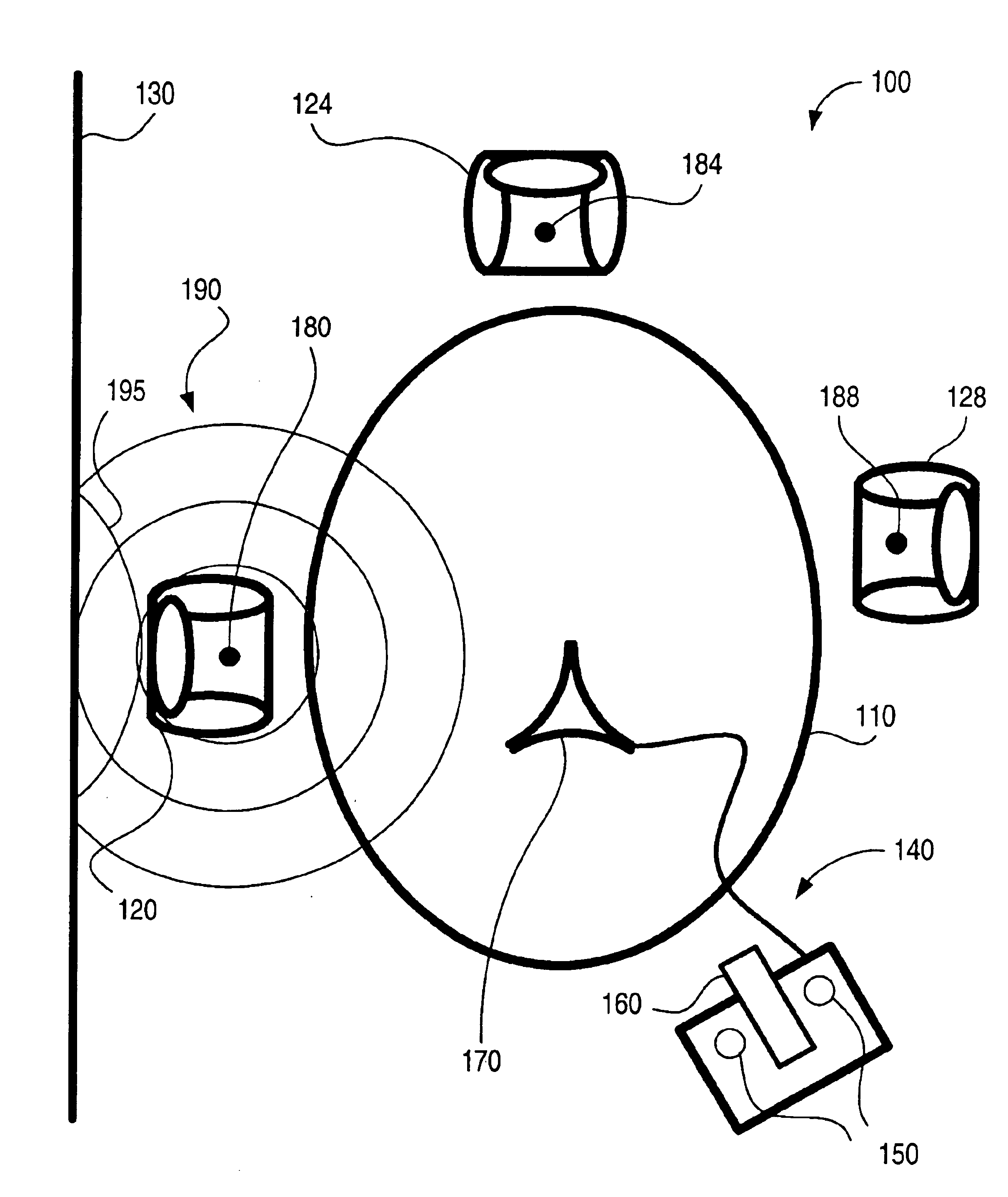
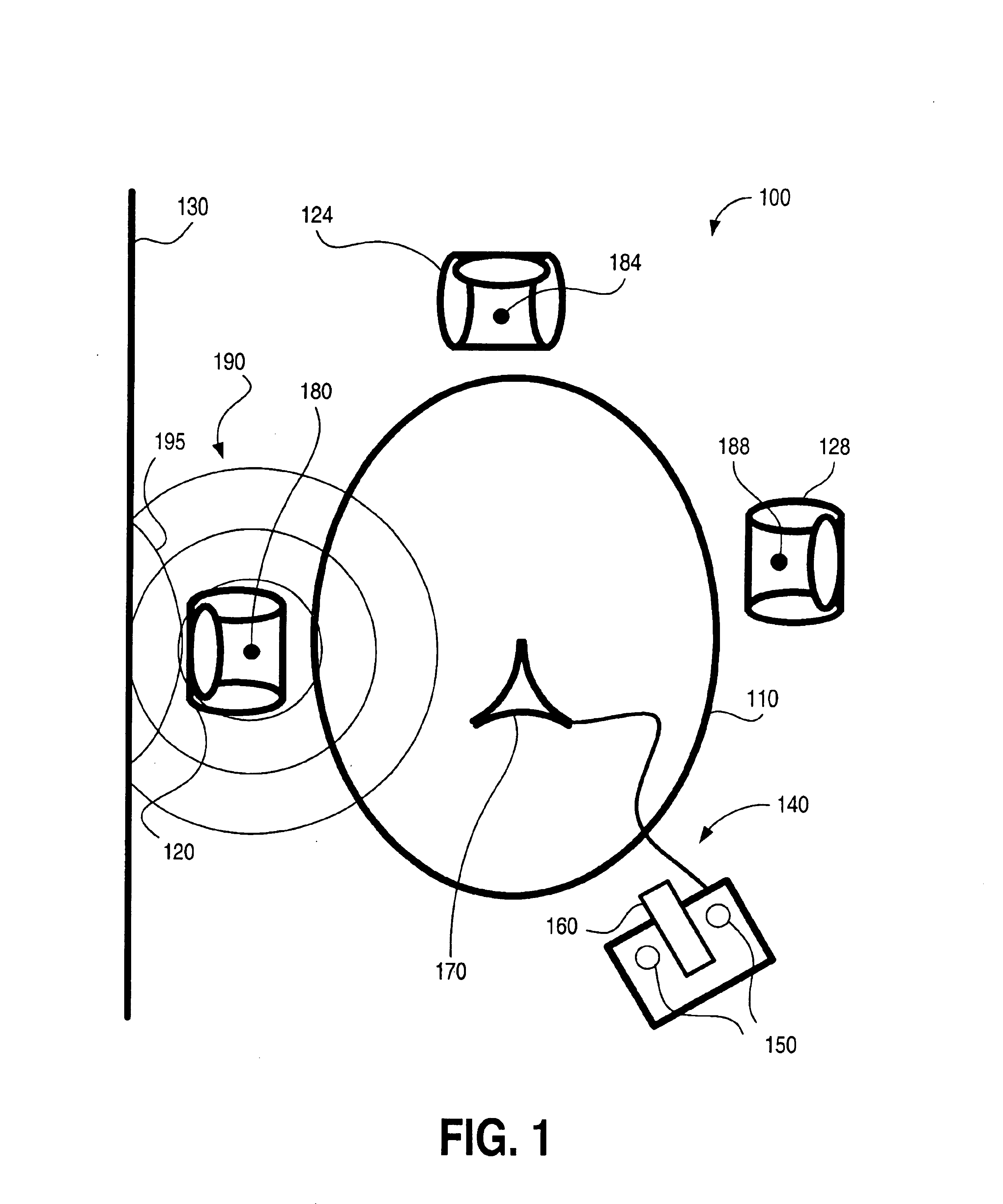
[0026]FIG. 1 shows a conference room 100. Room 100 has a table 110, three chairs 120, 124, and 128, a wall 130, and a videoconferencing system 140. Videoconferencing system 140 includes a microphone array 150, a video camera 160 and a movable microphone 170.

[0027]Movable microphone 170 receives the sound that is transmitted as the audio component of the teleconference to a remote location. Movable microphone 170 is typically kept away from video camera 160 so it does not pick up extraneous noise from the normal operation of video camera 160.

[0028]In one embodiment of the invention, microphone array 150 is positioned proximate to video camera 160. As will be described, microphone array 150 consists of at least two microphones, although a typical system would includes five or six microphones. Additionally, if the location of movable microphone 170 relative to videoconferencing system 140 was known, microphone 170 could also be configured to act as part of microphone array 150. In orde...


PUM


Abstract

An acoustic tracking system that uses an array of microphones to determine the location of an acoustical source. Several points in space are determined to be potential locations of an acoustical source. Beamforming parameters for the array of microphones are determined at each potential location. The beamforming parameters are applied to the sound received by the microphone array for all of the potential locations and data is gathered for each beam. The most likely location is then determined by comparing the data from each beam. Once the location is determined, a camera is directed toward this source.

Description

BACKGROUND OF THE INVENTION[0001]1. Field of the Invention[0002]The invention relates generally to videoconferencing systems and more specifically to camera tracking of videoconference participants.[0003]2. Description of Related Art[0004]When people wish to communicate from remote locations, a videoconferencing system is a convenient way to share ideas. Typically, there is more than one person participating in a videoconference. A camera must, therefore, be positioned to frame everyone in the room. However, such camera shots are impersonal and do not allow the recipient of the image to pick up on nuances of the speaker's facial expressions because they lack sufficient detail. Manually tracking the camera from one speaker to the next is inconvenient and distracting. There are a number of prior art patents in this field directed to solving this problem.[0005]For example, U.S. Pat. No. 5,686,957 to Baker teaches automatic tracking by using a plurality of microphones and a crude audio ...

Claims


Application Information

Patent Timeline
IPC IPC(8): G01S3/808H04N7/14
CPCG01S3/8083H04N7/142
Inventor MCCASKILL, JOHN
Owner HEWLETT PACKARD DEV CO LP
Learn More