Control system for a vertical vane covering for architectural openings

Inactive Publication Date: 2006-01-10
HUNTER DOUGLAS INC
View PDF39 Cites 10 Cited by
  • Summary
  • Abstract
  • Description
  • Claims
  • Application Information

AI Technical Summary

Benefits of technology

[0023]Each carrier has a pair of engaged gears with one gear being a worm gear mounted on the tilt rod for unitary rotation therewith, and the second gear being a pinion gear associated with a hanger pin from which a vane is suspended. The carriers have been designed so that the pantograph interconnection with the carriers is centered over the tilt rod so as to minimize skewing of the carriers on the tilt rod upon expansion and contraction of the pantograph.
[0024]Each hanger pin has a pair of depending legs adapted to capture a vane therebetween. The vane is provided with an opening near its upper edge and one leg of the hanger pin has a hook that is removably r

Problems solved by technology

One problem with prior art control systems has been the manner in which the carriers are connected to the pantograph.
Typically, due to the central connection system and expansion of the pantograph upon movement of the lead carrier, the other carriers are caused to skew slightly resulting in increased friction and making them more difficult to move along the length of the tilt rod.
Another shortcoming in prior art systems which utilize pull cords to move the lead carrier is the fact that the pulleys for returning and deflecting the pull cords are normally relatively small in size thereby requiring multiple revolutions to allow significant movement of the carriers which increases system friction and imposes unnecessary wear on the system.
Another problem with prior art control systems resides in the fact that they are difficult to assemble inasmuch as the drive mechanism of the carriers associated with the vanes must be uniformly aligned and operably connected to the tilt rod so that pivotal movement of the tilt rod moves the vanes between associated and corresponding angular positions.
Accordingly, if the carriers are not mounted on the tilt rod uniformly, the vanes will not be properly aligned and uniformly angularly related to the architectural opening.
As will be appreciated, in order to properly align and uniformly angularly relate the vanes to the architectural opening, the carriers have to be carefully and uniformly mounted on the tilt rod, which can be a time consuming endeavor.
Still another prevailing problem with prior art control systems for vertical vane coverings resides in

Method used


Image

  • Control system for a vertical vane covering for architectural openings
  • Control system for a vertical vane covering for architectural openings
  • Control system for a vertical vane covering for architectural openings

Examples


Embodiment Construction

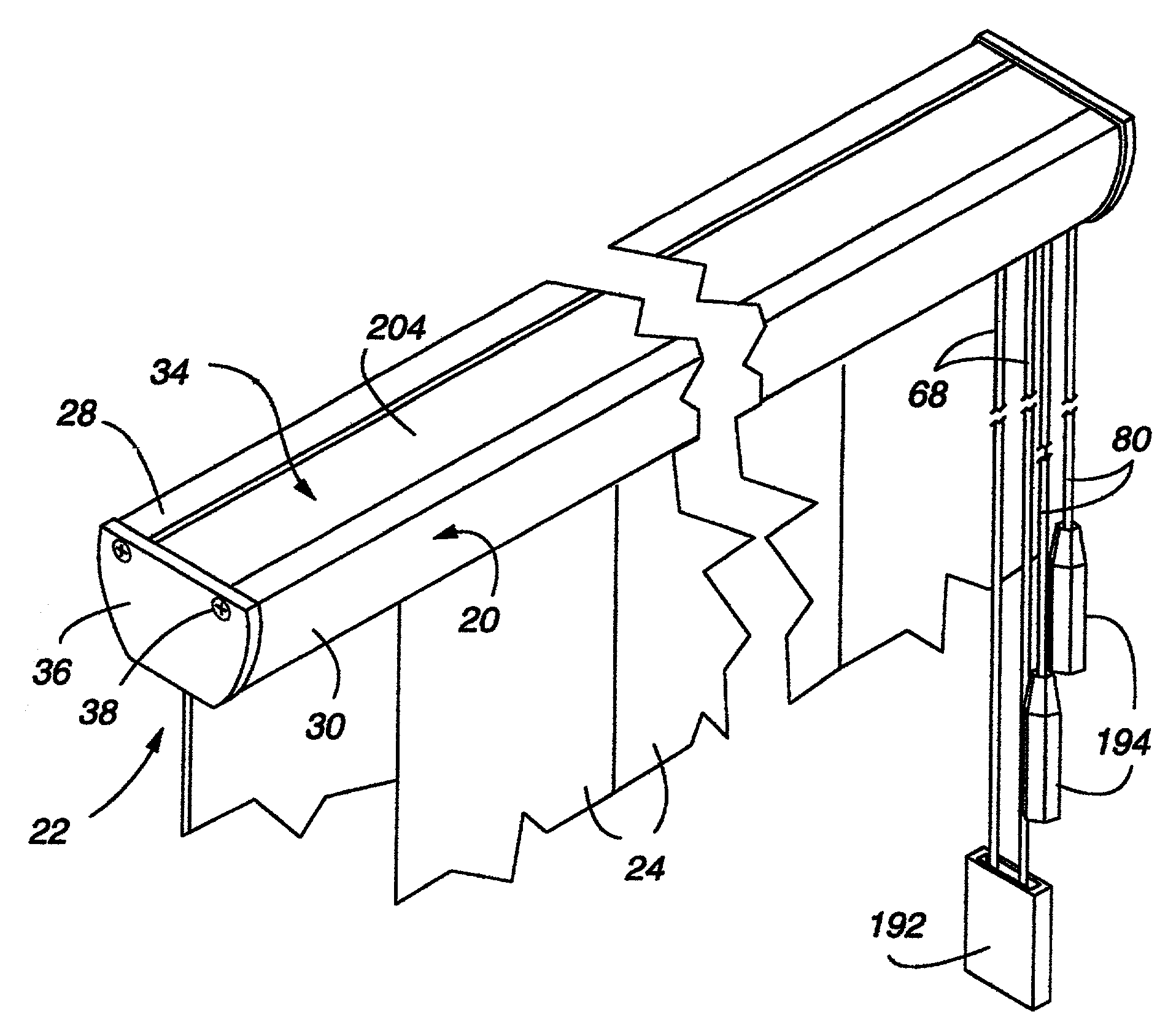
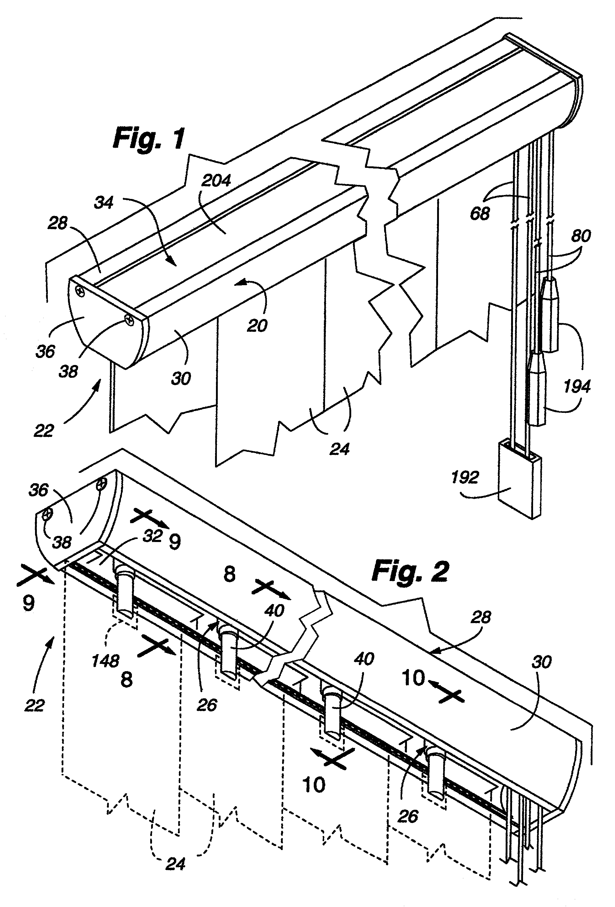
[0102]The headrail 20 and other portions of the control system 22 of the present invention are shown in FIGS. 1 and 2 with vertical covering segments, hereafter referred to as vanes 24 but which might assume other configurations, being suspended from carriers 26 in the system in adjacent side by side relationship. For purposes of clarity, the vanes are shown in dashed lines in FIG. 2. The headrail for the control system is designed to extend completely across the top of an architectural opening (not shown), and be suspended in a manner to be described hereafter from a beam or other supporting structure at the top of the architectural opening. While not being illustrated, the control system 22 is adapted to move the vanes 24 from a retracted position wherein the vanes are horizontally stacked adjacent one side of the architectural opening to an extended position wherein the vanes are evenly distributed across the architectural opening. In the extended position the vanes are adapted t...


PUM


Abstract

A control system for a vertical vane covering for an architectural opening includes a new and improved symmetric headrail having uniquely designed carriers for suspending individual vanes wherein the carriers are designed to minimize skewing relative to a tilt rod as they are moved along the headrail. A pantograph system is utilized to interconnect the carriers, and is connected to the carriers in alignment with the tilt rod so as to minimize skewing. The carriers have pockets formed therein through which the traverse cord extends so that the traverse cord, which moves the carriers along the tilt rod, is secured to a lead carrier closely adjacent to the tilt rod to, again, minimize skewing. Light blocking rails are also attachable to the headrail to substantially bridge the gap between the headrail and the top of the suspended vanes to prevent light from passing therebetween. The tilt rod is keyed to gears in the carriers to facilitate assembly of the control system with all vanes properly aligned.

Description

CROSS-REFERENCE TO RELATED APPLICATIONS[0001]The present application is a continuation of U.S. application Ser. No. 09 / 996,638, filed 28 Nov. 2001 ('638 application), now U.S. Pat. No. 6,408,924, which is a continuation of U.S. application Ser. No. 09 / 592,510, filed 12 Jun. 2000 ('510 application), now abandoned, which is a continuation of U.S. application Ser. No. 08 / 915,793, filed 21 Aug. 1997 ('793 application), now U.S. Pat. No. 6,116,322, which is a continuation-in-part of U.S. application Ser. No. 08 / 724,576, filed Sep. 30, 1996 ('576 application), now U.S. Pat. No. 6,135,188, and which claims priority to U.S. provisional application No. 60 / 047,075, filed 19 May 1997 ('075 application). Each of the '638, '510, '793, '075, and '576 applications is hereby incorporated by reference as though fully disclosed herein.BACKGROUND OF THE INVENTION[0002]1. Field of the Invention[0003]The present invention relates generally to coverings for architectural openings such as doors, windows, ...

Claims


Application Information

Patent Timeline
IPC IPC(8): E06B9/36
CPCE06B9/36
Inventor ANDERSON, RICHARD N.THOMPSON, EUGENE W.
Owner HUNTER DOUGLAS INC
Why Eureka
Try Eureka