Display driving method and display apparatus utilizing the same

a technology of display apparatus and driving method, applied in the field of display apparatus, can solve the problem of limited display luminance of display apparatus, and achieve the effect of increasing the peak luminance of an image displayed

Inactive Publication Date: 2006-01-10
CANON KK
View PDF26 Cites 33 Cited by
  • Summary
  • Abstract
  • Description
  • Claims
  • Application Information

AI Technical Summary

Benefits of technology

[0016]An object of the present invention is to provide a display driving method capable of obtaining a quality image by increasing the peak luminance of an image displayed, and to provide a display apparatus utilizing the driving method.
[0017]Another object of the present invention is to provide a display driving method capable of obtaining a quality image by avoiding a wasteful period, and to provide a display apparatus utilizing the driving method.

Problems solved by technology

However, in display apparatus of so-called line sequential scanning that employs time division to select scanning wirings one at a time as described above, the maximum light emission time of each pixel generally cannot exceed the length of selection period within a horizontal scanning period and the display luminance of the display apparatus is accordingly limited.

Method used


Image

  • Display driving method and display apparatus utilizing the same
  • Display driving method and display apparatus utilizing the same
  • Display driving method and display apparatus utilizing the same

Examples


embodiment 1

(Embodiment 1)

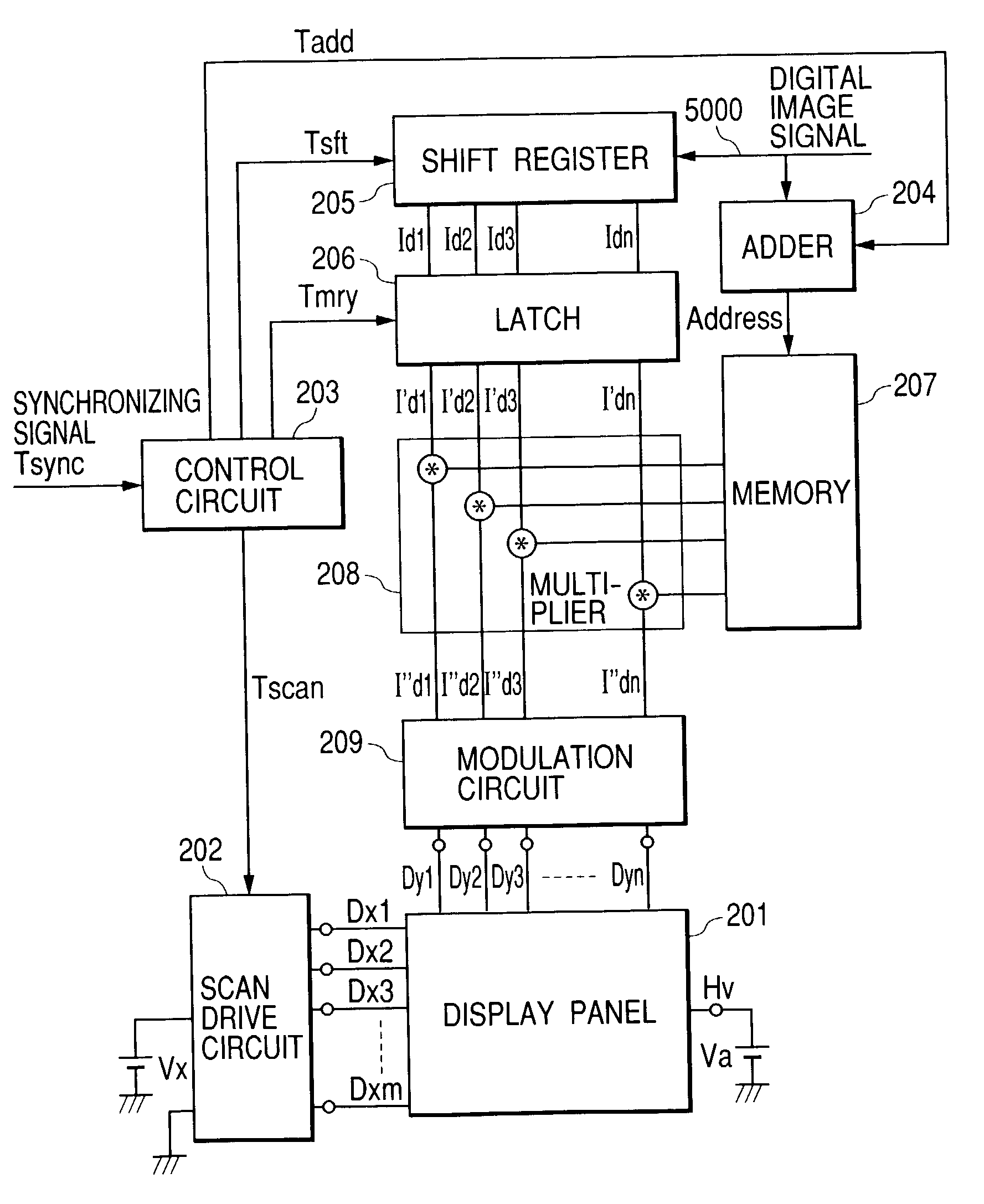
[0171]A structure provided with a multi-electron source is known in which N rows of cold cathode devices (display devices) and M columns of cold cathode devices, N×M in total, are arranged two-dimensionally to form a matrix pattern, and the cold cathode devices are wired by passive matrix wiring using M row-directional wirings (scanning wirings) placed in the row direction and N column-directional wirings (modulation wirings) placed in the column direction.

[0172]For multiplexing driving of a large number of cold cathode devices that are wired by matrix wiring, one row of devices of the matrix (devices of one row are connected to one row-directional wiring) are driven simultaneously.

[0173]To elaborate, a given selection voltage is applied to one row-directional wiring while applying a given modulation voltage to column-directional wirings that are connected to the cold cathode devices to be driven among the N cold cathode devices connected to the one row-directional wir...

embodiment 2

(Embodiment 2)

[0526]In Embodiment 1, display horizontal scanning periods are allotted by display scanning period calculation processing to the respective lines such that each display horizontal scanning period contains the maximum value maxDi of adjusted image data detected by the detector 22 of line maximum value as described above. This makes it possible to correct voltage drop of a scanning wiring and at the same time display an image without lowering the luminance. However, depending on the image to be displayed, the total length of the horizontal scanning periods which is the sum of one frame of allotted display horizontal scanning periods exceeds one frame period of input image. This embodiment deals with this problem and improves Embodiment 1.

[0527]The difference between Embodiment 1 and this embodiment is that, when a display horizontal scanning period is simply allotted to a scanning line so as to contain the maximum value maxDi of adjusted image data for the scanning line,...

embodiment 3

(Embodiment 3)

[0594]Described next is Embodiment 3 of the present invention.

[0595]The difference between this embodiment and Embodiment 2 is that the two take different approaches to a situation in which a display horizontal scanning period is simply allotted to a scanning line so as to contain the maximum value maxDi of adjusted image data of pixels on each scanning line, and the total length of similarly allotted horizontal scanning periods exceeds one frame period of an input image signal. The rest of Embodiment 3 is identical with Embodiment 2.

[0596]In Embodiment 2, the display horizontal scanning period KHDi is adjusted by the gain YG and the adjusted image data is multiplied by the gain DGAIN so that the maximum pulse width of a modulation signal associated with the display horizontal scanning period KHDi is contained within the adjusted display horizontal scanning period KHDi. Then the pulse width is modulated to generate a modulation signal.

[0597]In this embodiment, the puls...


PUM


Abstract

In order to obtain a satisfactory image by making a peak luminance of an image to be displayed large and suppressing an occurrence of unnecessary period, there is provided a display driving method for driving a display with a plurality of scanning wirings and a plurality of modulation wirings, comprising: a step of supplying a scan selection signal to a scanning wiring selected out of the plural scanning wirings for each horizontal scanning period; and a step of supplying a modulation signal modulated in accordance with image data to the plural modulation wirings for each horizontal scanning period, in which the selection period of the scan selection signal varies between at least two horizontal scanning periods in a vertical scanning period.

Description

BACKGROUND OF THE INVENTION[0001]1. Field of the Invention[0002]The present invention relates to display apparatus for displaying an image with a display device such as an electron-emitting device, an electroluminescent (EL) device, an LED device, a plasma light-emitting device, and a liquid crystal device, and to a method of driving the display apparatus.[0003]Specifically, the invention relates to a multiplexing drive method for a matrix display with a plurality of self-luminous display devices arranged to form a matrix pattern.[0004]2. Related Background Art[0005]The above plural display devices control, to display images, signals that are to be supplied to a matrix wiring consisting of a plurality of row-directional wirings (scanning wirings) and a plurality of column-directional wirings (modulation wirings).[0006]Hereinafter matrix displays are described taking as an example a self-luminous display that uses light emitted from a phosphor to form an image.[0007]In this type of d...

Claims


Application Information

Patent Timeline
Patent Type & Authority Patents(United States)
IPC IPC(8): G09G5/00G09G3/20G09G3/22G09G5/02
CPCG09G3/20G09G3/2014G09G3/2003G09G3/22G09G2360/18G09G2320/0223G09G2320/0276G09G2360/16G09G2310/0267
Inventor ABE, NAOTOSAGANO, OSAMUANDO, MUNEKISAITO, HIROSHI
Owner CANON KK
Why Eureka
Try Eureka