Apparatus and method of controlling brightness of image

a technology of brightness control and apparatus, applied in the direction of television system, color signal processing circuit, instruments, etc., can solve the problems of increasing the brightness of an image without keeping the original hue or/and chroma, and the brightness of an image is limited by the brightness control circuit of the conventional image, etc., to achieve the effect of increasing the brightness of an imag

Inactive Publication Date: 2007-09-11
SAMSUNG ELECTRONICS CO LTD
View PDF10 Cites 22 Cited by
  • Summary
  • Abstract
  • Description
  • Claims
  • Application Information

AI Technical Summary

Benefits of technology

[0010]To solve the above-described problems, it is a first object of the present invention to provide an image brightness controlling apparatus and method capable of maintaining the sense of color (e.g., hue, chroma, or the like) of an image while increasing the brightness of an image.

Problems solved by technology

Accordingly, a conventional image brightness control circuit has a limit in increasing the brightness of an image.
However, this method may cause a problem in that colors that can be reproduced are out of the color gamut.
This gamut problem means that a luminance signal Y with an increased brightness does not have two corresponding color-difference signals.
In this case, an increased brightness image does not keep the original hue or / and chroma.
This may cause degradation in the quality of image.
However, in this histogram equalization, the vector direction of an output color may be changed from the vector direction of an input color, which leads to color variation.

Method used


Image

  • Apparatus and method of controlling brightness of image
  • Apparatus and method of controlling brightness of image
  • Apparatus and method of controlling brightness of image

Examples


first embodiment

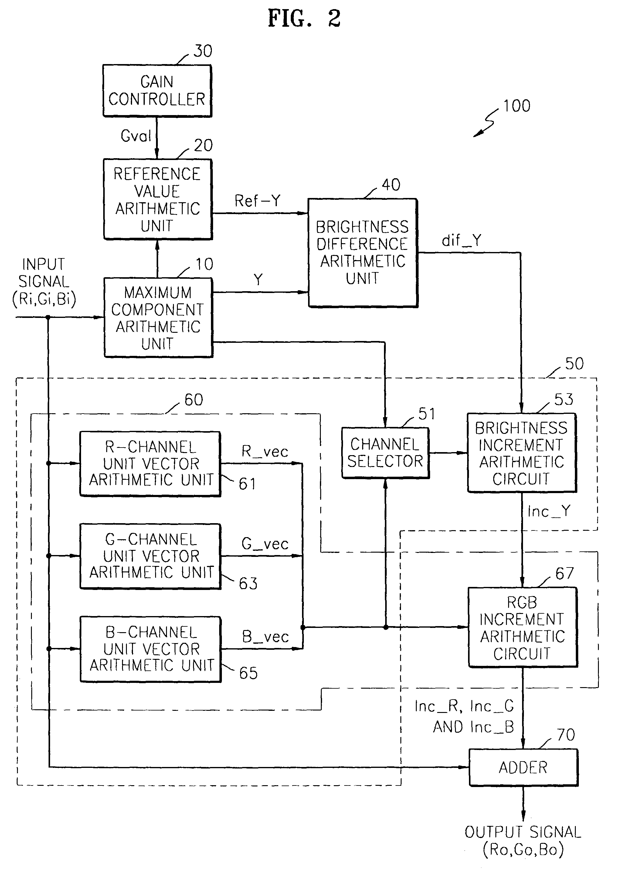
[0066]FIG. 2 is a block diagram of an image brightness controlling apparatus according to the present invention. Referring to FIG. 2, an image brightness controlling apparatus 100 includes a maximum component arithmetic unit 10, a reference value arithmetic unit 20, a gain controller 30, a brightness difference arithmetic unit 40, a brightness increment arithmetic unit 50, an RGB increment arithmetic unit 60, and an adder 70.

[0067]The brightness increment arithmetic unit 50 includes an R-channel unit vector arithmetic unit 61, a G-channel unit vector arithmetic unit 63, a B-channel unit vector arithmetic unit 65, a channel selector 51, and a brightness increment arithmetic circuit 53. The RGB increment arithmetic unit 60 includes the R-, G-, and B-channel unit vector arithmetic units 61, 63 and 65, and the RGB increment arithmetic circuit 67.

[0068]The maximum component arithmetic unit 10 receives three red, green, and blue signals (or components) Ri, Gi, and Bi constituting an input...

second embodiment

[0076]FIG. 3 is a block diagram of an image brightness controlling apparatus according to the present invention. An image brightness controlling apparatus 200 in FIG. 3 includes a reference value arithmetic unit 20, a gain controller 30, a brightness arithmetic unit 110, a brightness increment arithmetic unit 130, an RGB increment arithmetic unit 60, and an adder 70. Since the image brightness controlling apparatus 200 of FIG. 3 is similar to the image brightness controlling apparatus 100 of FIG. 2, only the brightness arithmetic unit 110 and the brightness increment arithmetic unit 130 will now be described.

[0077]The brightness arithmetic unit 110 calculates the brightness Y of an input signal composed of R, G and B signals Ri, Gi and Bi and outputs the same to the reference value arithmetic unit 20 and the brightness increment arithmetic unit 130. The brightness increment arithmetic unit 130 calculates the brightness difference dif_Y between the reference brightness Ref_Y output f...

third embodiment

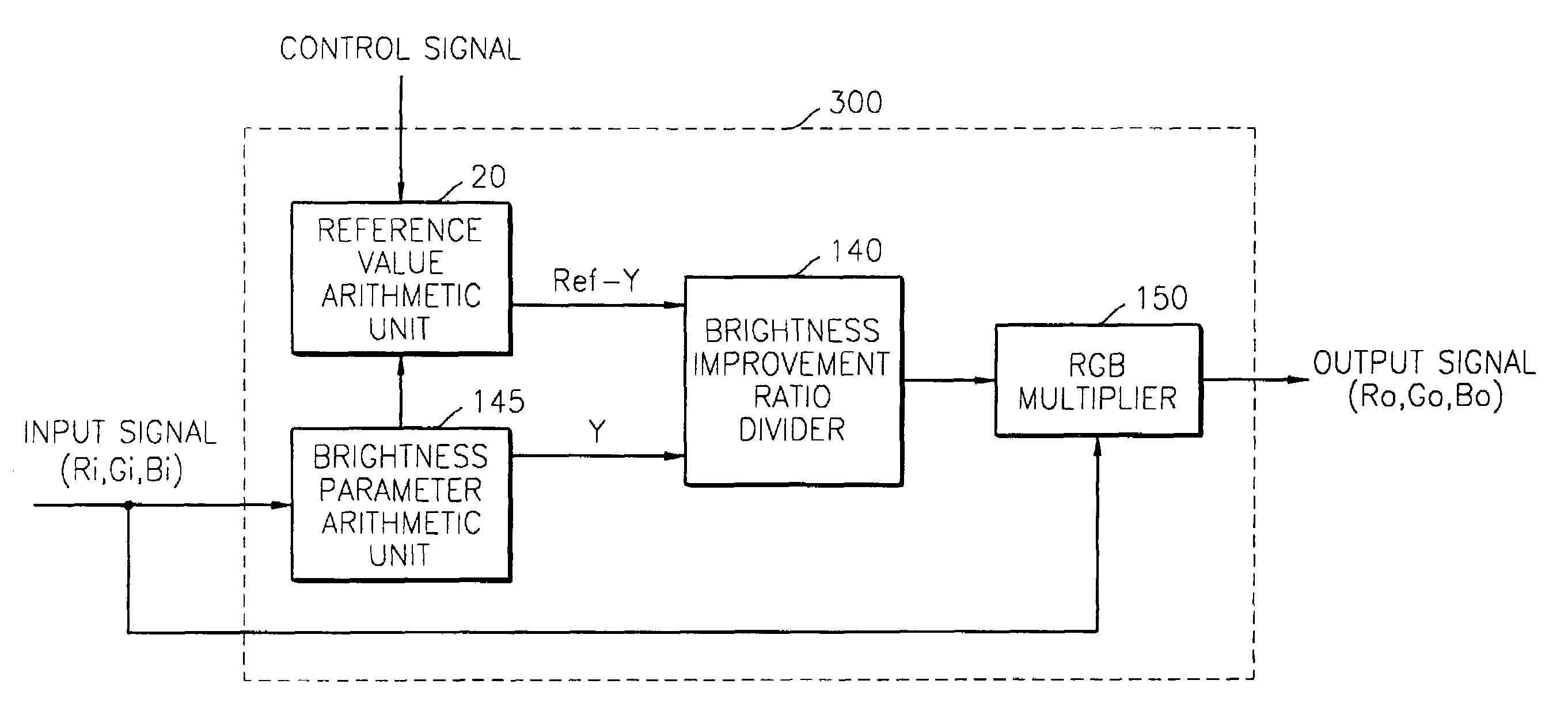
[0079]FIG. 4 is a block diagram of an image brightness controlling apparatus according to the present invention. An image brightness controlling apparatus 300 of FIG. 4 includes a brightness parameter arithmetic unit 145, a reference value arithmetic unit 20, a brightness improvement ratio divider 140, and an RGB multiplier 150.

[0080]The brightness parameter arithmetic unit 145 receives an image signal (Ri, Gi, and Bi), determines the brightness parameter of the received image signal, and outputs the same to the reference value arithmetic unit 20 and the brightness improvement ratio divider 140. The brightness parameter can be determined by a plurality of methods. For example, the maximum value out of three components Ri, Gi, and Bi constituting the received image signal can be determined as the brightness parameter.

[0081]The reference value arithmetic unit 20 is the same as the reference value arithmetic unit described above, so it will not be described in detail.

[0082]The brightne...


PUM


Abstract

Provided are an image brightness controlling apparatus and method, and an adaptive brightness controlling apparatus and method based on the brightness degree and / or brightness range of an image. The image brightness controlling apparatus includes a brightness increment arithmetic unit for outputting a brightness increment for a pixel, and an individual component brightness increment arithmetic unit for outputting the brightness increments of individual components constituting the pixel in response to the brightness increment for a pixel. The individual component brightness increment arithmetic unit multiplies the brightness increment of the pixel by each of the unit vectors of the components constituting the pixel to obtain the brightness increments of the individual components. The image brightness controlling apparatus further includes an adder for adding the components constituting the pixel to the brightness increments of the components. The image brightness controlling apparatus and the adaptive image brightness controlling apparatus can maintain the sense of color of an image (e.g., the hue or chroma of an image) while increasing the brightness degree and brightness range of an image.

Description

CROSS-REFERENCE TO RELATED APPLICATIONS[0001]This application is based upon and claims priority from Korean Patent Application Nos. 2001-88233 filed Dec. 29, 2001 and 2002-23726 filed Apr. 30, 2002, the contents of which are incorporated herein by reference.BACKGROUND OF THE INVENTION[0002]1. Field of the Invention[0003]The present invention relates to brightness control circuits, and more particularly, to an image brightness controlling apparatus and method, and an adaptive image brightness controlling apparatus and method based on the brightness degree and / or brightness range of an image, these apparatuses and methods being capable of maintaining the sense of color, such as the original hue (color tone) or chroma, while increasing the brightness of the entire image or part of the image displayed on an image display device, such as a display monitor or a color TV.[0004]2. Description of the Related Art[0005]An image brightness controlling apparatus is a circuit for controlling the ...

Claims


Application Information

Patent Timeline
Patent Type & Authority Patents(United States)
IPC IPC(8): G09G3/30H04N5/57H04N9/77
CPCH04N9/77H04N9/68
Inventor LEE, SEONG-DEOKKIM, CHANG-YEONGSEO, YANG-SEOCKHAN, YONG-IN
Owner SAMSUNG ELECTRONICS CO LTD
Why Eureka
Try Eureka