Latch device

Active Publication Date: 2006-01-17
NIFCO INC
View PDF13 Cites 24 Cited by
  • Summary
  • Abstract
  • Description
  • Claims
  • Application Information

AI Technical Summary

Problems solved by technology

Accordingly, due to a single lock mechanism, strength of locking the movable member is

Method used


Image

  • Latch device
  • Latch device
  • Latch device

Examples


Embodiment Construction

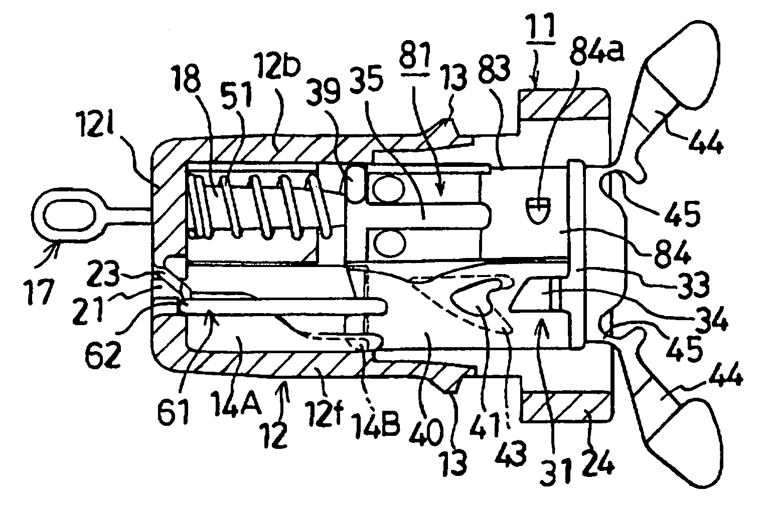
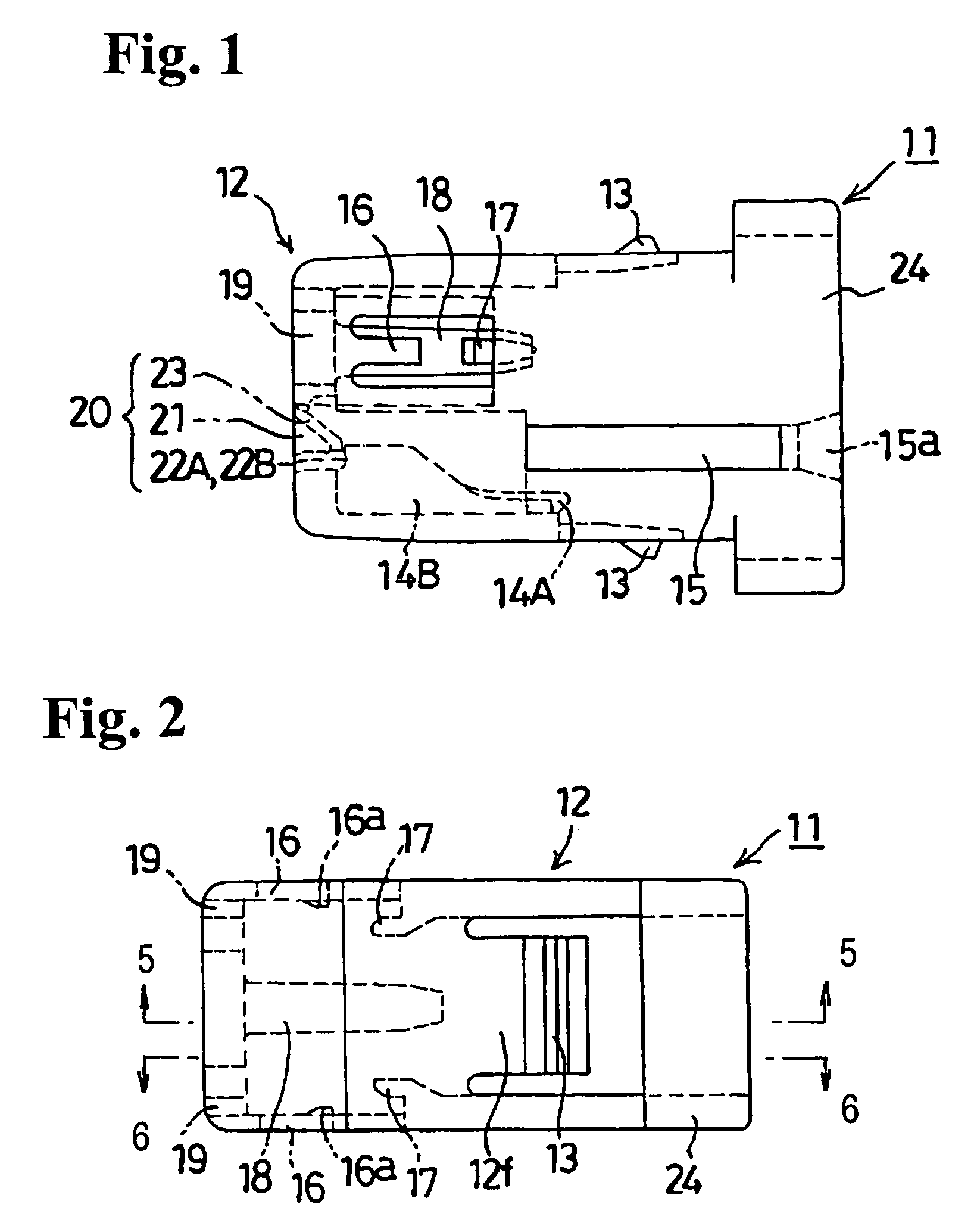
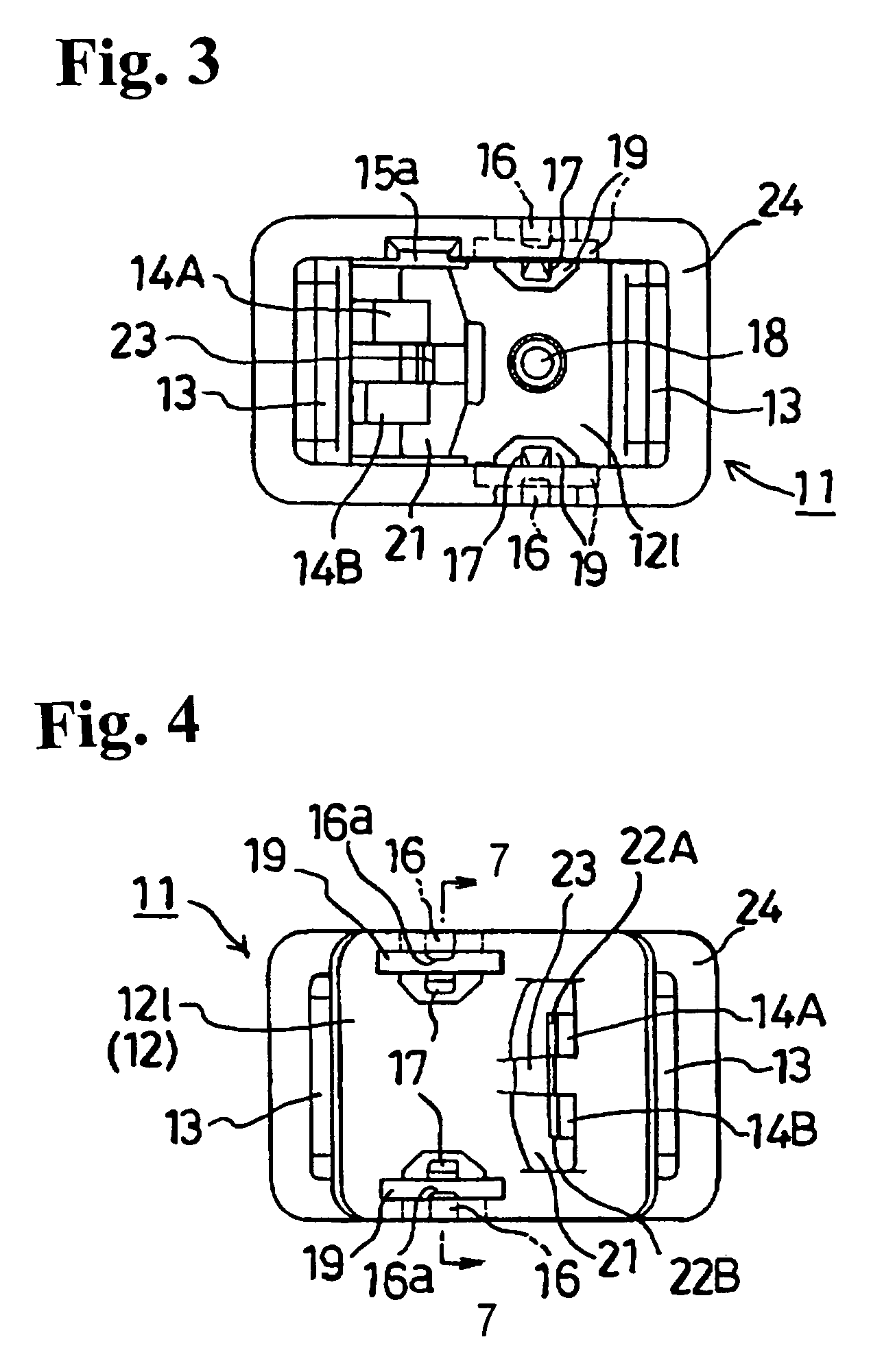
[0034]Hereunder, embodiments of the present invention will be explained with reference to the accompanying drawings. FIG. 1 is a plan view of a housing composing a latch device according to an embodiment of the present invention. FIG. 2 is a front view of the housing shown in FIG. 1; FIG. 3 is a right side view of the housing shown in FIG. 1; and FIG. 4 is a left side view of the housing shown in FIG. 1. FIG. 5 is a cross sectional view taken along line 5—5 in FIG. 2; FIG. 6 is a cross sectional view taken along line 6—6 in FIG. 2; and FIG. 7 is a cross sectional view taken along line 7—7 in FIG. 4. A guide groove communicating with a guide long hole is shown at an upper left of FIG. 7. Hereinafter, up and down directions, and right and left directions correspond to the front view of each member.

[0035]In FIGS. 1 to 7, a housing 11 is formed of a synthetic resin. The housing 11 is composed of a box portion 12 having a front surface wall 12f, a back surface wall 12b, a ceiling wall 12...


PUM


Abstract

A latch device includes a movable member and a housing. The movable member is urged with an urging member to a position where a part of the movable member projects from the housing. When the movable member is pushed into the housing against a force of the urging member, a push-push type lock mechanism turns to a lock state and the movable member is locked at a push-in position. When the movable member in the push-in position is pushed into the housing again against the force of the urging member, the lock mechanism turns to an unlock state, so that the movable member is returned to the projecting position. The lock mechanism is provided on front and back surfaces of the movable member as well as on portions of the housing facing the front and back surfaces of the movable member.

Description

BACKGROUND OF THE INVENTION AND RELATED ART STATEMENT[0001]The present invention relates to a latch device. The latch device is provided with a switch and is attached to an attached member such as a main member of a radio cassette player, so that a door member of the radio cassette is closed or opened when the door member is pushed.[0002]A conventional latch device includes a movable member and a housing. The movable member is urged with an urging member to a position where a part of the movable member projects from the housing. When the movable member is pushed into the housing against a force of the urging member, the movable member is locked at a push-in position where a push-push type lock mechanism turns to a locked state and the switch is turned on. When the movable member in the push-in position is pushed into the housing again against the force of the urging member, the lock mechanism turns to an unlocked state, so that the movable member is returned to the projecting positi...

Claims


Application Information

Patent Timeline
IPC IPC(8): E05B15/02E05B17/22E05C19/02H01H3/16H01H13/18H01H13/56
CPCE05C19/022H01H27/00H01H13/562H01H13/183E05B17/22H01H3/163Y10S292/04Y10T292/0833Y10T292/696E05C19/02
Inventor KAWAMOTO, MASANOBUTOMITA, SHIGEMITSU
Owner NIFCO INC
Why Eureka
Try Eureka