Floor rack for holding a paper towel roll and the like

a technology for floor racks and paper towels, applied in the field of floor racks, can solve the problems of defective design of prior art floor racks and lack of means

Inactive Publication Date: 2006-01-24
LAI MING HSIAO
View PDF4 Cites 27 Cited by
  • Summary
  • Abstract
  • Description
  • Claims
  • Application Information

AI Technical Summary

Problems solved by technology

Such a prior art floor rack as described above is defective in design in that it is not pr...

Method used


Image

  • Floor rack for holding a paper towel roll and the like
  • Floor rack for holding a paper towel roll and the like
  • Floor rack for holding a paper towel roll and the like

Examples


Embodiment Construction

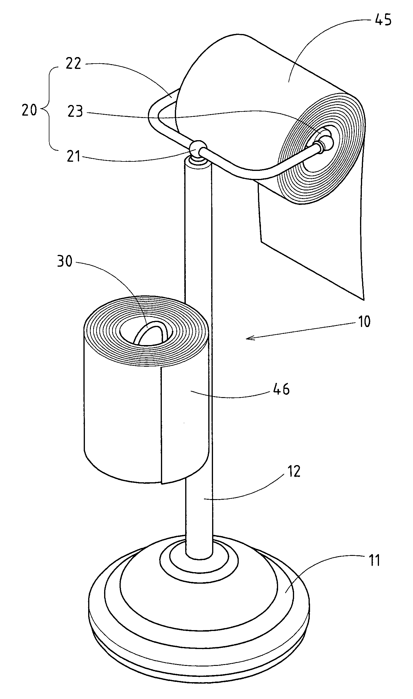
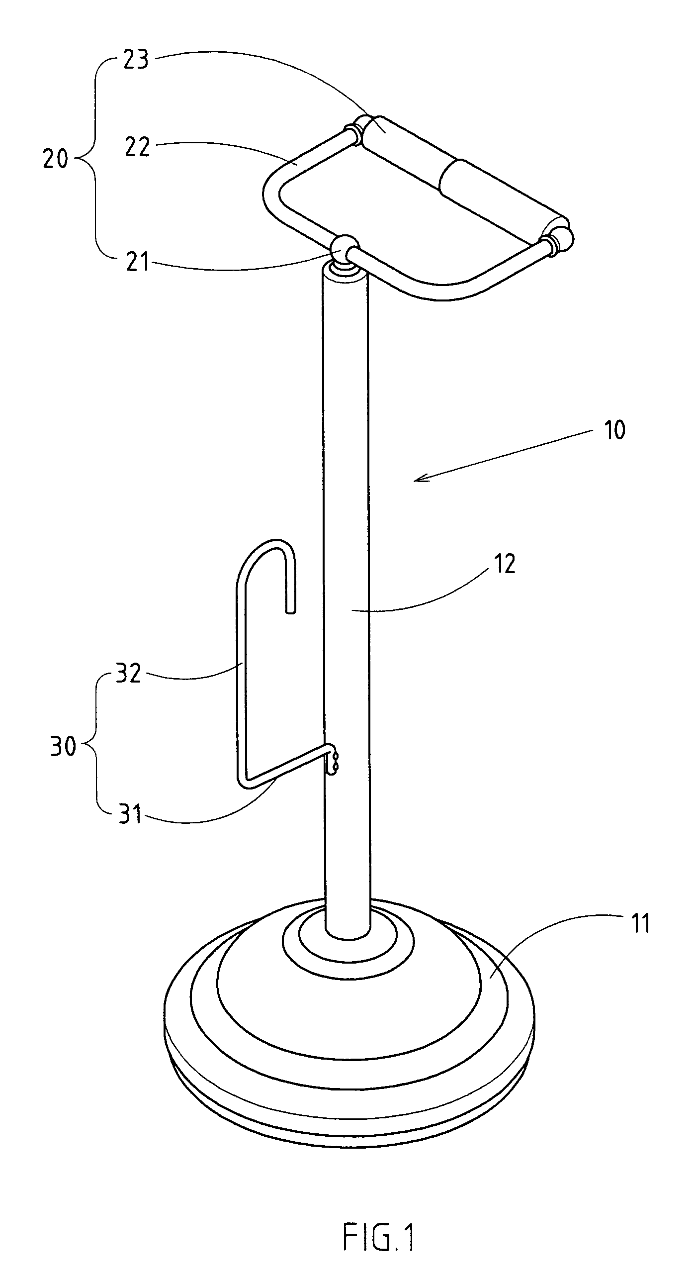
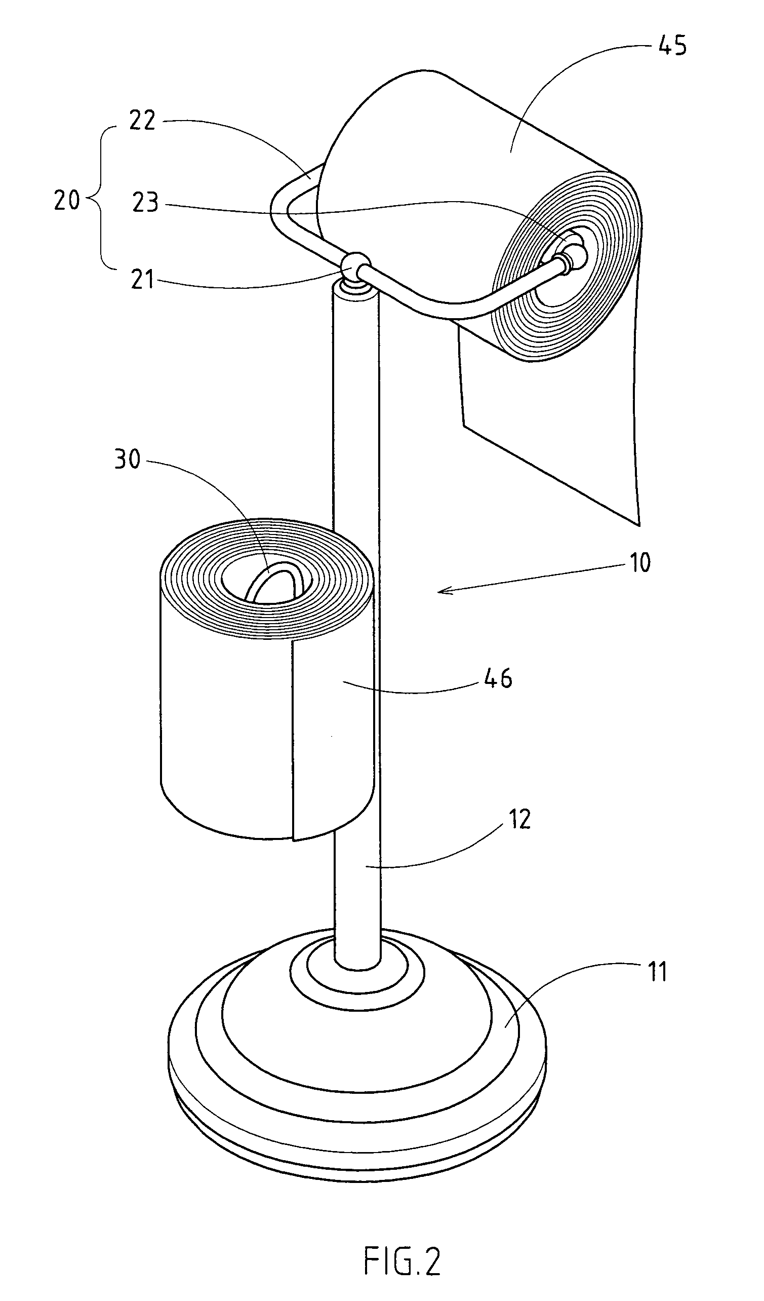
[0015]As shown in FIGS. 1 and 2, a floor rack 10 embodied in the present invention comprises a base 11, a support post 12 extending uprightly from the base 11, a first holder 20 for holding a paper towel roll 45 ready to serve, and a second holder 30 for holding a standby paper towel roll 46.

[0016]The first holder 20 is formed of a fastening portion 21, a support frame 22, and a holding rod 23 for holding a paper towel roll 45. The fastening portion 21 is fastened to a top end of the support post 12.

[0017]The second holder 30 has a fastening arm 31 and a holding arm 32 extending from the fastening arm 31 such that the holding arm 32 is perpendicular to the fastening arm 31. The fastening arm 31 is fastened at one end by welding to a lower segment of the upright support post 12. The holding arm 32 is used to hold the standby paper towel roll 46.

[0018]As shown in FIGS. 3–6, the present invention comprises a second holder 40 which is detachably fastened at one end to the lower segment ...


PUM


Abstract

A floor rack is designed to hold a plurality of paper towel rolls and is formed of a base, a support post, a first holder, and one or more second holders. The support post is uprightly extended from the base. The first holder is fastened with a top end of the support post for holding a paper towel roll ready to serve. The second holders are fastened to the support post for holding a plurality of standby paper towel rolls.

Description

RELATED U.S. APPLICATIONS[0001]Not applicable.STATEMENT REGARDING FEDERALLY SPONSORED RESEARCH OR DEVELOPMENT[0002]Not applicable.REFERENCE TO MICROFICHE APPENDIX[0003]Not applicable.FIELD OF THE INVENTION[0004]The present invention relates to a floor rack for holding paper towel rolls. The floor rack is provided with means to hold a standby paper towel roll.BACKGROUND OF THE INVENTION[0005]As shown in FIG. 7, a floor rack of the prior art comprises a base 50, an upright support post 51, and a paper towel holder 52. Such a prior art floor rack as described above is defective in design in that it is not provided with means to hold a paper towel roll which can be put into service on an emergency basis.BRIEF SUMMARY OF THE INVENTION[0006]The primary objective of the present invention is to provide a floor rack for holding paper towel rolls. The floor rack comprises a first holder and a second holder. The first holder is used to hold a paper towel roll ready to serve, while the second h...

Claims


Application Information

Patent Timeline
IPC IPC(8): B65H16/02
CPCA47K10/38A47K2010/3253
Inventor LAI, MING-HSIAO
Owner LAI MING HSIAO
Why Eureka
Try Eureka