Vehicle having a movable driving position

a technology of non-mechanical and by-wire driving position, which is applied in the direction of movable seats, transportation and packaging, propulsion unit arrangements, etc., can solve the problems of less than optimal convenience for the driver, inherently more difficult to control the steering, braking and acceleration functions of the vehicle from different positions spaced from the original seat position, and control of the control of the vehicle from different positions

Inactive Publication Date: 2006-01-31
GM GLOBAL TECH OPERATIONS LLC
View PDF31 Cites 51 Cited by
  • Summary
  • Abstract
  • Description
  • Claims
  • Application Information

AI Technical Summary

Benefits of technology

[0004]This invention is based on a method of mechanization utilizing drive-by-wire for drive, steer, brake, throttle, etc. where the driver's seat with the vehicle controls can move into optimal seating positions within a vehicle. The method of movement is based on the concept in one embodiment of a carousel or merry-go-round. The driver's seat and the passenger seat are adjacent to one another on a platform that moves or revolves in a circular pattern. The two seats rotate around a center point of the carousel which houses a wire bundle passing vehicle control data from the vehicle chassis to the driver's vehicle controls. The driver's vehicle control interface in this concept provides one method of vehicle control with the vehicle's foot operations being integrated into the driver's vehicle interface, or steering wheel. This arrangement enables the driver to accelerate, brake, stop, start, or turn from one location. The technical advantage of this arrangement is the flexibility to drive the vehicle from different positions within the vehicle. In this one embodiment, there are four seat positions in this invention forming a diamond pattern; left-hand drive, right-hand drive, center-front drive, and center-rear drive. As the carousel revolves, the seats are designed to face in the forward direction the vehicle is traveling. However, each seat may also swivel or rotate so that the driver may face rearwardly. Other advantages may include fold-down seat backs that turn into tables or other holding devices for the interior of the vehicle.

Problems solved by technology

By-wire steering, braking and acceleration controls and control systems on a vehicle are not designed to accomodate a change in position of a driver.
Thus, although a prior art vehicle may include a driver's seat that is rotatable, allowing the driver to shift his position, the controls typically do not move to accommodate the change in position.
These system limitations create less than optimal convenience for the driver.
Controlling the steering, braking and acceleration functions of a vehicle from different positions spaced from the original seat position is inherently more difficult.

Method used


Image

  • Vehicle having a movable driving position
  • Vehicle having a movable driving position
  • Vehicle having a movable driving position

Examples


Embodiment Construction

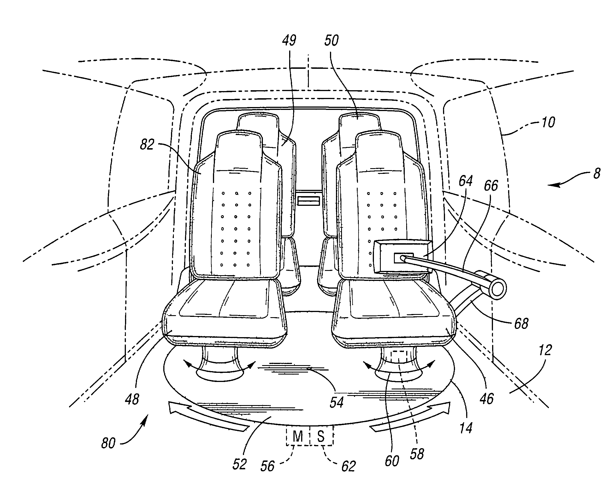
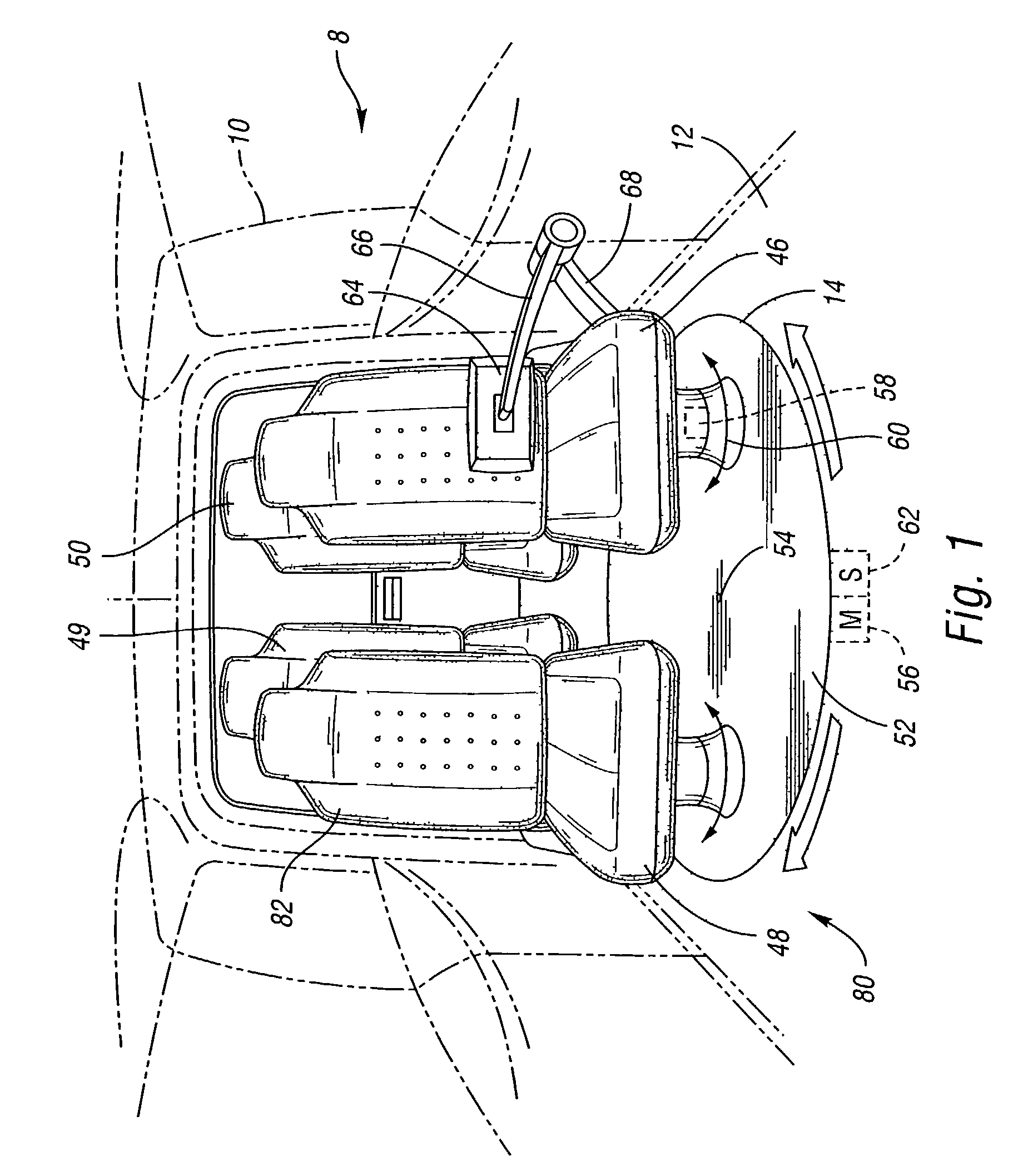
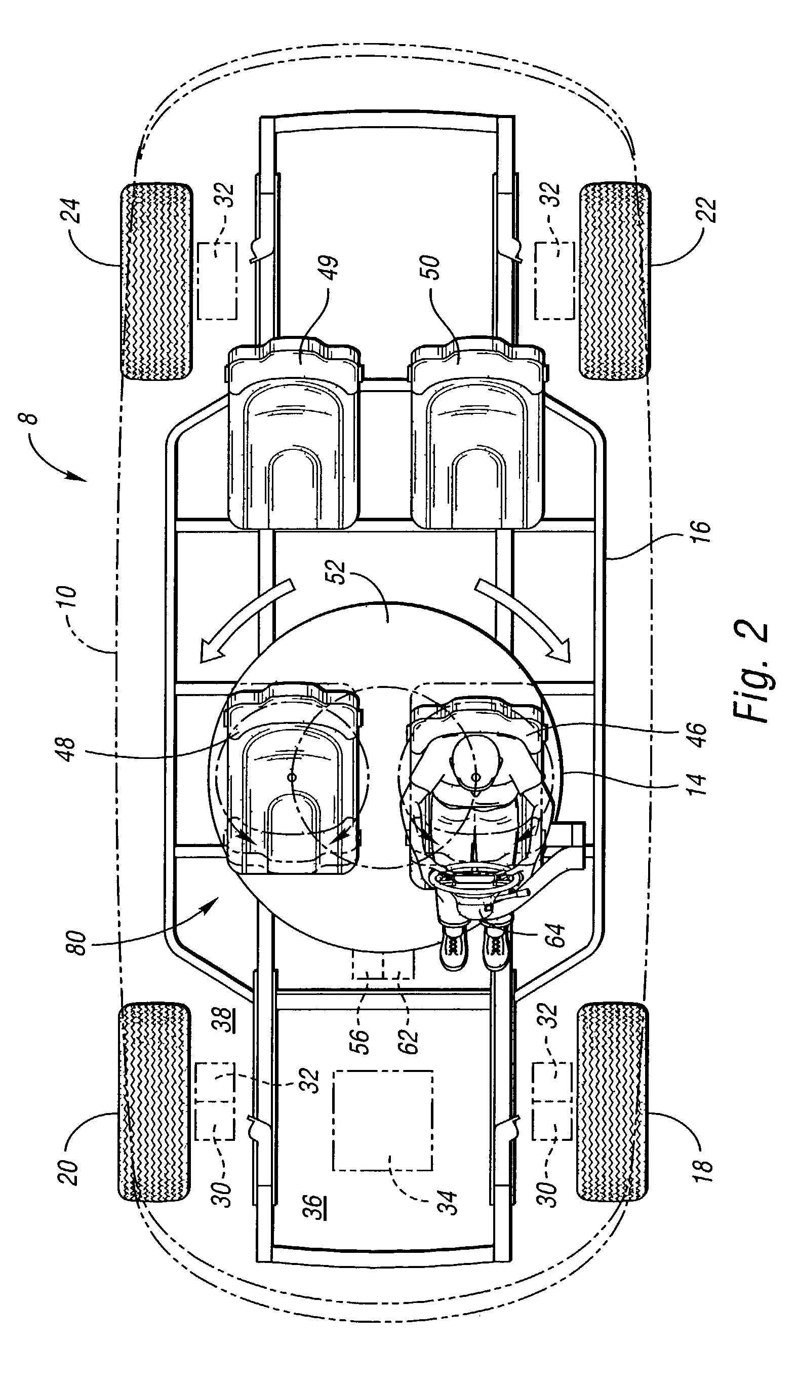
[0024]Referring to FIG. 1, a vehicle 8 in accordance with the invention includes a body 10 (in phantom), a standard thin chassis or rolling platform 12 and a driver's seat assembly or carousel 14. The vehicle 8 is preferably an automobile but the invention also contemplates that the vehicle may be a tractor or other industrial or commercial vehicle such as a bus. The invention also has utility in a non-automotive vehicle.

[0025]The chassis, also referred to herein as the rolling platform 12, includes a frame 16 having four wheels 18, 20, 22, 24 that are operable with respect to the frame 16, see FIG. 2. The chassis or rolling platform 12 together with the body 10 defines a vehicle, preferably an automobile, but the invention also contemplates that the vehicle may be a tractor, bus, or other industrial or commercial vehicle. Those skilled in the art will recognize materials and fastening methods suitable for attaching the wheels 18, 20, 22 and 24 to the frame 16.

[0026]The chassis 12 f...


PUM


Abstract

A vehicle has multiple movable driving positions resulting from a seat which is movable with respect to the vehicle chassis and has a driver's vehicle interface which moves with the seat. A wire bundle interconnects the driver's vehicle interface with controls for driving the vehicle. In one embodiment, a carousel rotates and a seat on the carousel revolves and rotates so that the seat continues to face forward.

Description

CROSS REFERENCE TO RELATED APPLICATIONS[0001]This application claims the benefit of U.S. Provisional Application 60 / 341,517 filed Dec. 13, 2001, which is hereby incorporated by reference.TECHNICAL FIELD[0002]This invention relates to a non-mechanical (by-wire) driver control of a vehicle which permits the driver to face the direction of travel and control the vehicle from a plurality of movable driving positions.BACKGROUND OF THE INVENTION[0003]By-wire steering, braking and acceleration controls and control systems on a vehicle are not designed to accomodate a change in position of a driver. Thus, although a prior art vehicle may include a driver's seat that is rotatable, allowing the driver to shift his position, the controls typically do not move to accommodate the change in position. This requires that the driver navigate the vehicle from controls positioned to accommodate the driver in the original seat position. These system limitations create less than optimal convenience for ...

Claims


Application Information

Patent Timeline
Patent Type & Authority Patents(United States)
IPC IPC(8): B60K26/00B60N2/01B60N2/14
CPCB60N2/14B60N2/01
Inventor CHERNOFF, ADRIAN B.PAGLIANO, EUGENIO
Owner GM GLOBAL TECH OPERATIONS LLC
Why Eureka
Try Eureka