
Sealing mechanisms for use in liquid-storage containers

a sealing mechanism and liquid storage container technology, applied in the direction of sealing, liquid transfer devices, pliable tubular containers, etc., can solve the problems of paint waste, annular u-shaped channel, paint to be deposited in the annular u-shaped channel, etc., and achieve the effect of improving the sealing mechanism

Inactive Publication Date: 2006-02-14
RIEKE LLC
View PDF55 Cites 14 Cited by
  • Summary
  • Abstract
  • Description
  • Claims
  • Application Information

AI Technical Summary

Benefits of technology

[0013]One object of the present invention is to provide an...

Problems solved by technology

The awkwardness of pouring paint from the can into a tray for a roller is also seen as a drawback with this particular design.
Dipping a paint brush into the can and then using the can edge as a wiping edge also creates a mess and causes paint to be deposited in the annular U-shaped channel.
As paint collects in this peripheral channel, resealing the lid becomes particularly messy as the captured paint is pushed out and may either splatter or run down the side of the paint can.
Aside from the mess, the current metal paint can design results in wasted paint, not only from what drips, splatters, or runs down the side of the can, but also from not being able to tightly reseal the lid onto the can body.
If the lid is not tightly resealed on the can body, the paint can dry out or skim over, causing obvious problems of continued use and often resulting in the leftover portion of paint being discarded.
The attempt to incorporate this type of wiping edge as part of the pouring spout presents additional design challenges.
This tinting requires access to the interior of the paint container body and also requires some type of vibratory shaking of the paint container.

Method used


Image

  • Sealing mechanisms for use in liquid-storage containers
  • Sealing mechanisms for use in liquid-storage containers
  • Sealing mechanisms for use in liquid-storage containers

Examples


second embodiment

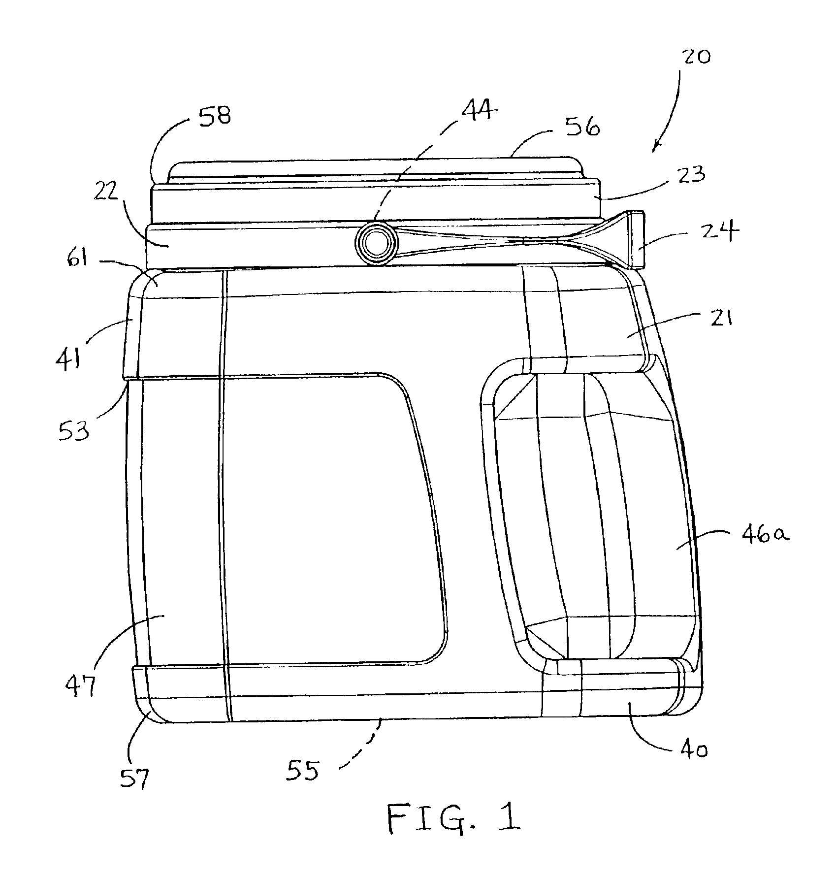
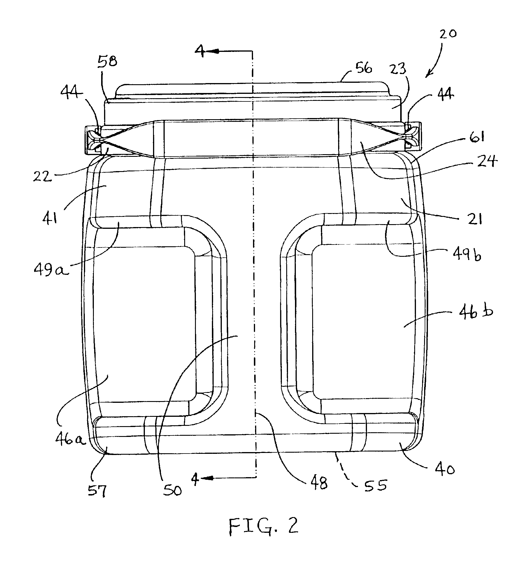
[0068]With references to FIGS. 6, 7, and 8, a second embodiment for a paint container 31 is illustrated. To begin, it should be understood that the same style of pouring spout 22 and handle 24 are used in this embodiment (container 31) and their attachment or engagement with the cap 32 and neck portion 26 are the same as that illustrated as part of paint container 20. The interior size and shape of the neck portion 26 of the FIGS. 6-8 container embodiment is substantially the same as the neck portion 26 of the FIGS. 1-5 container embodiment. As such, with the identical spout being used, the threaded engagement is the same and the surface-to-surface interference fit on the interior of the neck portion is the same.

[0069]The overall design of cap 32 is different from the overall design of cap 23, but the size, shape and arrangement of the interior of threaded outer wall 32a of cap 32 is virtually identical to the size, shape and arrangement of the interior of threaded outer wall 23a of...

third embodiment

[0074]With reference to FIGS. 9, 10, 11 and 12, a third embodiment for a paint container 36 is illustrated. To begin, it should be understood that virtually the same style of pouring spout 22′ is used in this embodiment (container 36) and its engagement with the cap 37 and with neck portion 26 is basically the same as that illustrated for spout 22 as part of paint containers 20 and 31. The one difference between spout 22′ and 22 is the elimination of pivot posts 44 from spout 22′. With regard to paint container 36, a hinged, bail-like handle is not used and thus there is no need for the handle pivot posts 44 as part of the annular collar 106. While this third preferred embodiment for a paint container includes a molded-in handle 35a, and thus the decision to not include a separate hinged, bail-like handle 24, spout 22′ could be replaced by spout 22 if such a handle might be desired as part of the overall container 36 design. Closing cap 37 of container 36 is virtually identical to c...


PUM


Abstract

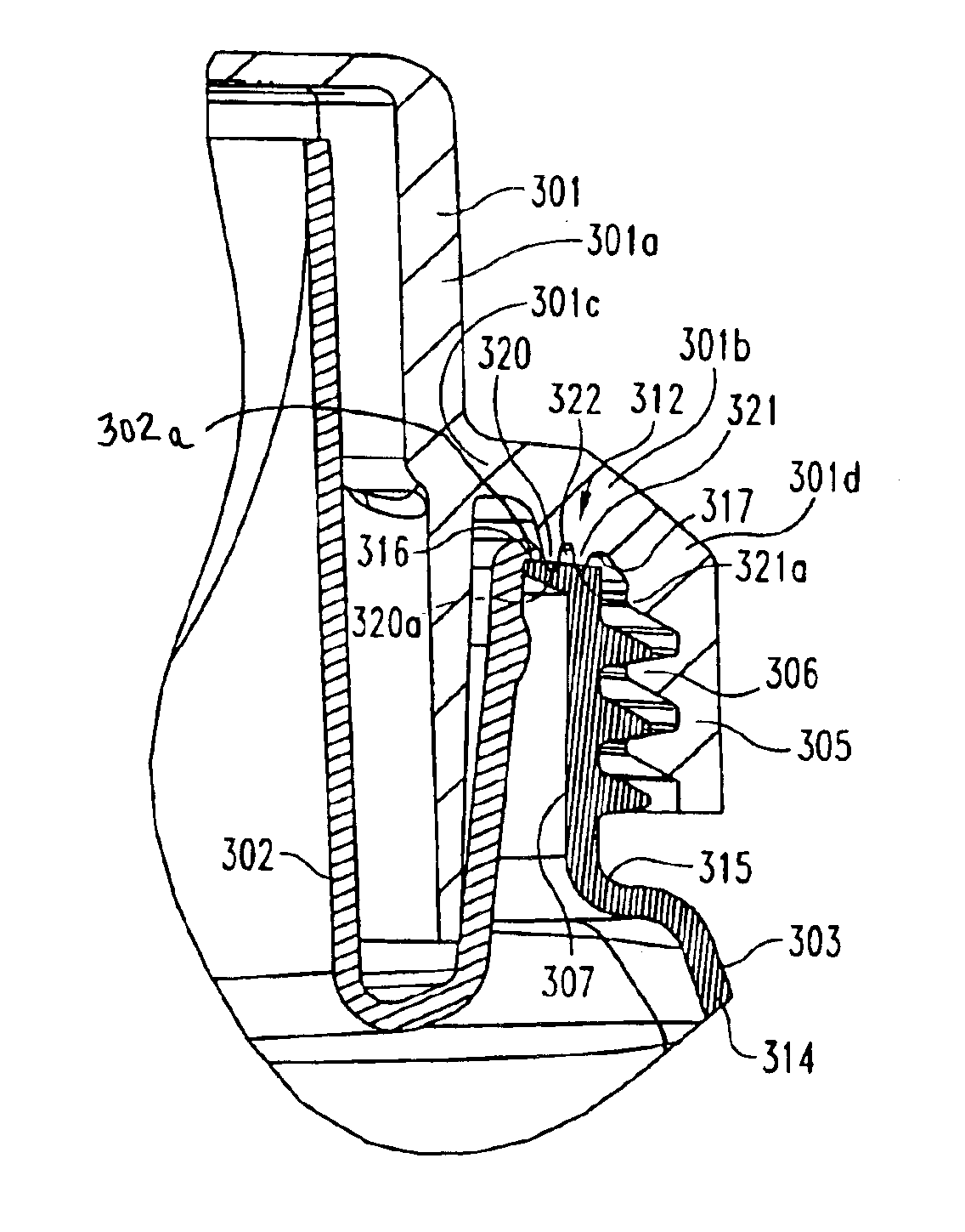
A container for the storage and dispensing of a liquid and which incorporates a sealing mechanism includes a blow-molded container body including a neck portion having a series of external threads and defining an annular, non-planar sealing surface, a pouring spout assembled into the body and a unitary closing lid including a series of internal threads constructed and arranged to engage the threads of the neck portion. The unitary closing lid includes the sealing mechanism in the form of a pair of annular sealing lips constructed and arranged to be compressed against the annular, non-planar sealing surface to establish a sealed interface between the closing lid and the body.

Description

REFERENCE TO RELATED APPLICATION[0001]This application is a Continuation-In-Part patent application of U.S. Ser. No. 10 / 199,618, filed Jul. 19, 2002, entitled Sealing Mechanisms for Use in Liquid-Storage Containers, which is now pending.BACKGROUND OF THE INVENTION[0002]The present invention relates in general to the sealing of an interface between two (or more) members, such as between a container body and a container lid.[0003]More specifically, the present invention relates to sealing mechanisms, structures, and techniques to be used in combination with liquid-storage containers which may be used to store (and dispense) various liquid substances such as paint, household cleaners, laundry products, and beverages, to name a few. The sealing mechanisms of the present invention may be formed portions of the actual members which define the interface to be sealed or may be separate sealing components or may be a combination of both.[0004]In the design of liquid-storage containers, a fir...

Claims


Application Information

Patent Timeline
IPC IPC(8): B67D1/16B65D25/28B65D25/32B65D47/12B65D47/40
CPCB65D25/2867B65D25/2885B65D25/2897B65D47/122B65D47/123B65D47/40B65D25/32B65D2543/00851
Inventor KASTING, THOMAS P.ROHR, ROBERT D.
Owner RIEKE LLC
Learn More