Board mounted power connector

a power connector and board mount technology, applied in the direction of line/current collector details, coupling device connections, printed circuits, etc., can solve problems such as myriad of problems

Active Publication Date: 2006-02-21
MOLEX INC
View PDF13 Cites 99 Cited by
  • Summary
  • Abstract
  • Description
  • Claims
  • Application Information

AI Technical Summary

Benefits of technology

[0013]Other objects, features and advantages of the invention will be apparent from the following detailed description taken in connection with the accompanying drawings.

Problems solved by technology

This creates a myriad of problems.

Method used


Image

  • Board mounted power connector
  • Board mounted power connector
  • Board mounted power connector

Examples


Embodiment Construction

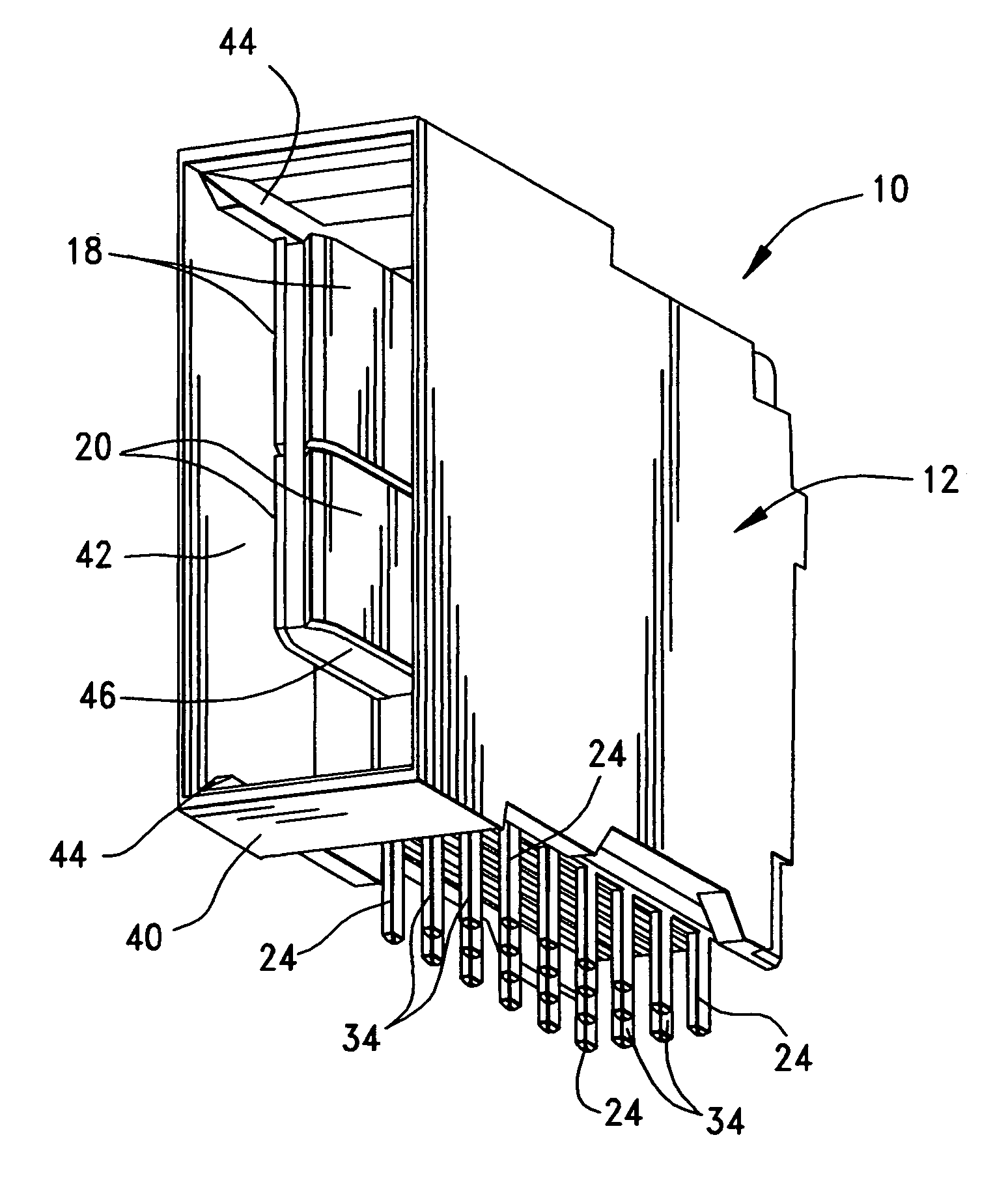
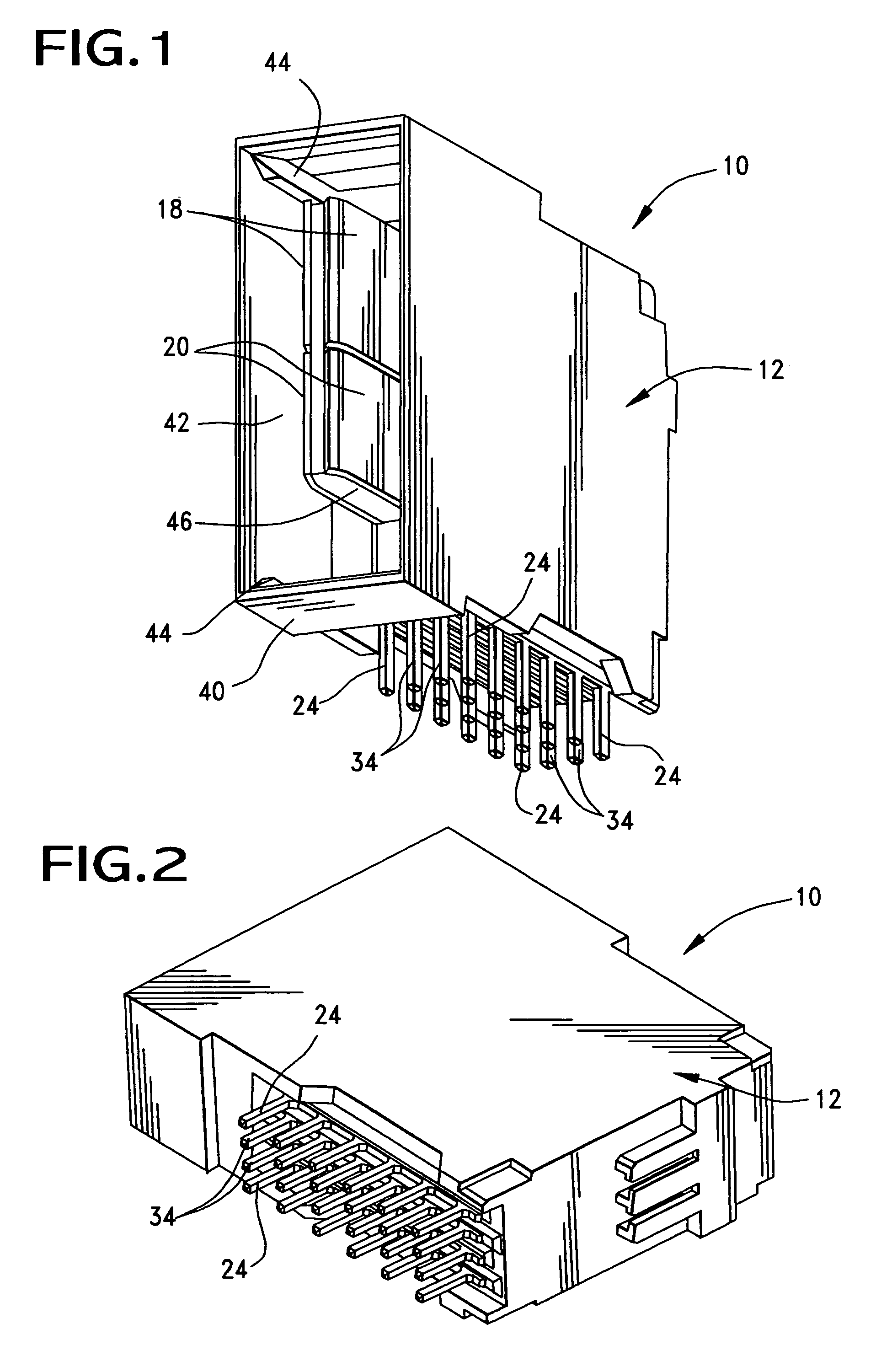
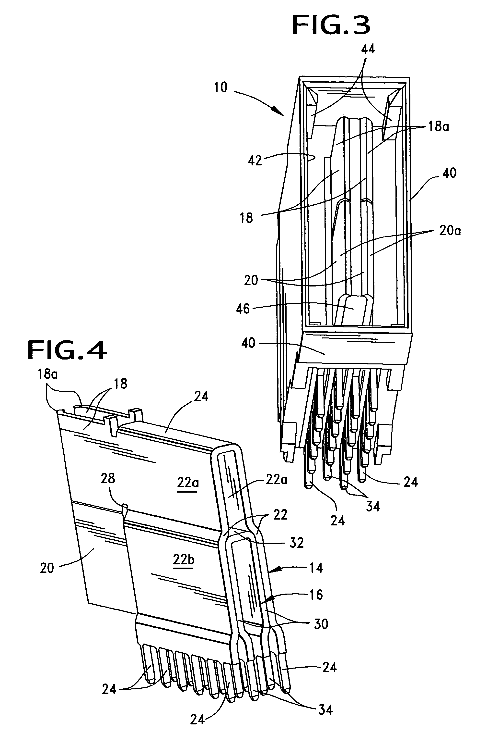
[0021]Referring to the drawings in greater detail, the invention is embodied in an electrical power connector, generally designated 10 and shown in FIGS. 1–3. The connector is extremely simple and includes a unitary, overmolded housing, generally designated 12, and outer and inner terminals, generally designated 14 and 16, respectively, in FIG. 4. Outer terminal 14 has a pair of blade portions 18, and inner terminal 16 has a pair of blade portions 20. The blade portions of one terminal are coplanar with the blade portions of the other terminal, and the two blade portions of each terminal are in spaced relationship as can be seen particularly in FIG. 3.

[0022]Referring to FIG. 5 in conjunction with FIG. 4, outer terminal 14 has a generally inverted U-shaped configuration. The outer terminal includes a pair of side walls 22 joined by a top connecting beam 24. Side walls 22 include upper sections 22a and lower sections 22b. A plurality of solder tails 24 project downwardly along a botto...


PUM


Abstract

An electrical power connector is mountable on a printed circuit board. The connector includes an outer terminal and an inner terminal, both of which are of generally inverted U-shaped configurations, with the inner terminal nested in the outer terminal. Solder tails project downwardly from bottom edges of side walls of the two terminals. Both terminals have a pair of blade portions projecting forwardly from the respective side walls of the terminals, whereby the blade portions of each terminal are spaced from each other. The blade portions of one terminal are generally coplanar with the blade portions of the other terminal. A dielectric housing is overmolded about the side walls of the outer terminal, leaving the solder tails and the outside surfaces of the blade portions exposed. The housing has a projecting portion extending into the spacing between the blade portions of the two terminals against the inside surfaces of the blade portions, leaving the outside surfaces of the blade portions exposed.

Description

FIELD OF THE INVENTION[0001]This invention generally relates to the art of electrical connector and, particularly, to a power connector and, still further, to a power connector for mounting on a printed circuit board.BACKGROUND OF THE INVENTION[0002]Generally, an electrical connector includes some form of dielectric or insulative housing which mounts one or more conductive terminals. The housing is configured for mating with a complementary mating connector or other connecting device which, itself, has one or more conductive terminals. A connector assembly typically includes a pair of mating connectors, such as plug and receptacle connectors sometimes called male and female connectors.[0003]Various types of electrical connectors are designed for mounting on a printed circuit board. The terminals have terminating ends for connection to appropriate circuit traces on the board, such as solder tails for solder connection to the circuit traces on the board and / or in holes in the board.[0...

Claims


Application Information

Patent Timeline
Patent Type & Authority Patents(United States)
IPC IPC(8): H01R12/00H01R12/71H01R12/57H01R12/58
CPCH01R43/0256Y10S439/947
Inventor MCGOWAN, DANIEL B.BOGIEL, STEVEN B.HENDRICKSON, WILLIAM P.PATEL, ARVINDPURKIS, TIMOTHY E.
Owner MOLEX INC
Why Eureka
Try Eureka