Connector for flex shaft for string trimmer

a technology of connecting rods and flex shafts, which is applied in the direction of rod connections, couplings, manufacturing tools, etc., can solve the problems of affecting the operation of the connection, the tendency of the connection to “strip” or break with use, and the inability to effectively and completely insert the working member into the connection

Inactive Publication Date: 2006-02-28
MTD PRODUCTS
View PDF39 Cites 19 Cited by
  • Summary
  • Abstract
  • Description
  • Claims
  • Application Information

AI Technical Summary

Problems solved by technology

Transmission may be over, under, or around obstacles or objects where transmission by solid shafts would be impractical or impossible.
One problem with existing flexible drive shaft connections is the tendency for the connection to “strip” or break with use.
Another problem with the existing connection designs is that it is difficult to effectively and completely insert the working member into the connection.
This causes improper performance of the combination and can result in damage to the connection and / or drive shaft.

Method used


Image

  • Connector for flex shaft for string trimmer
  • Connector for flex shaft for string trimmer
  • Connector for flex shaft for string trimmer

Examples


Embodiment Construction

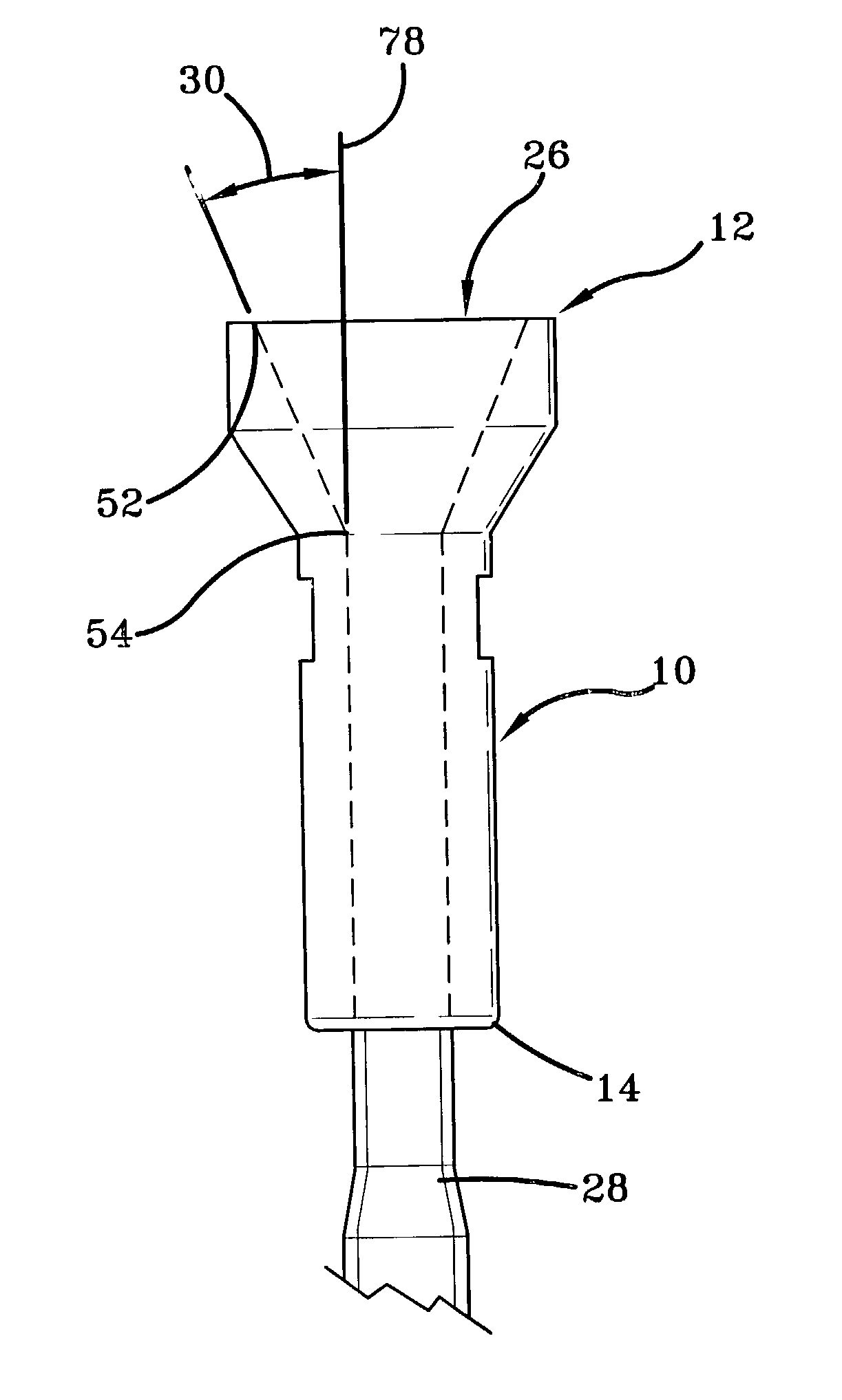
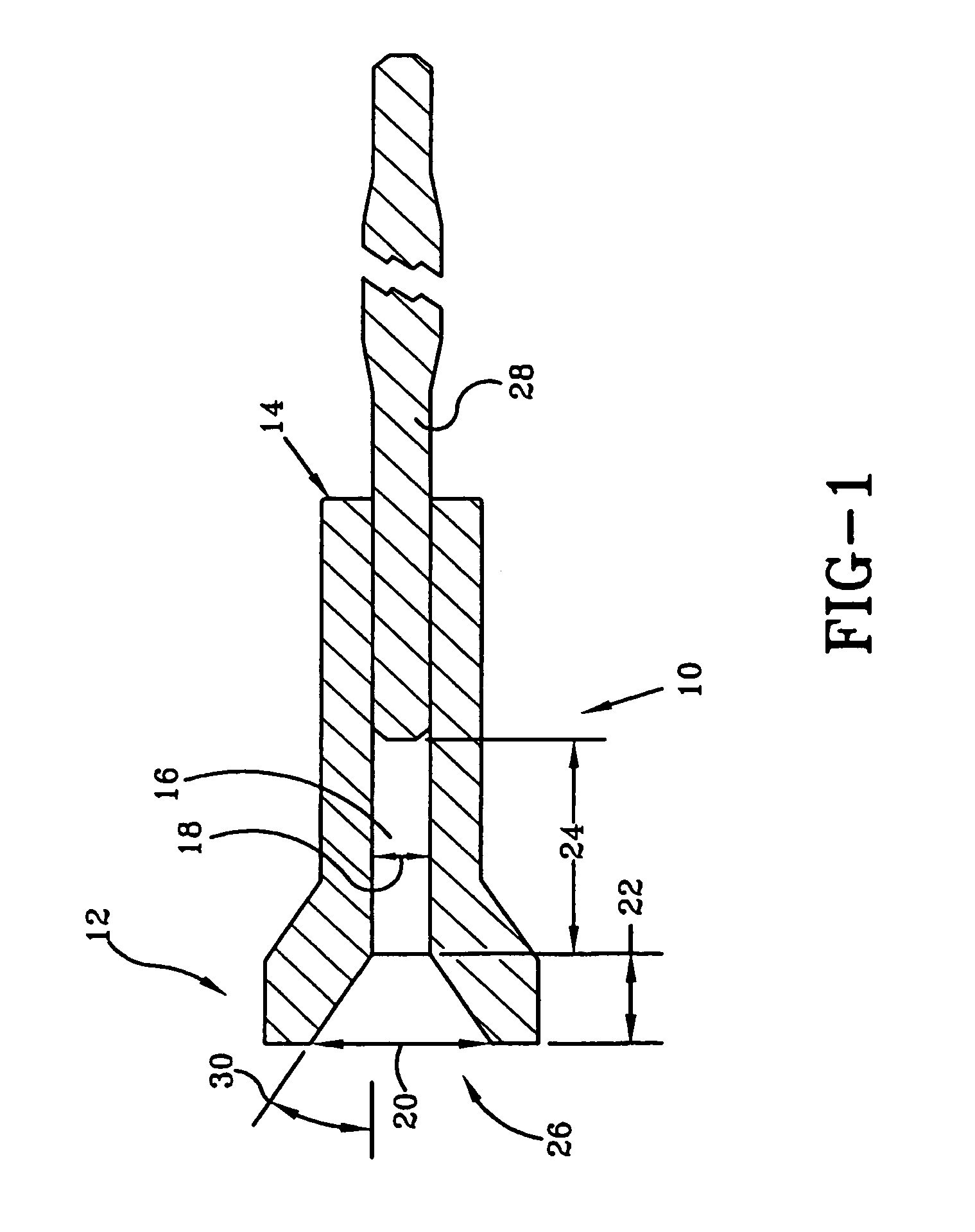
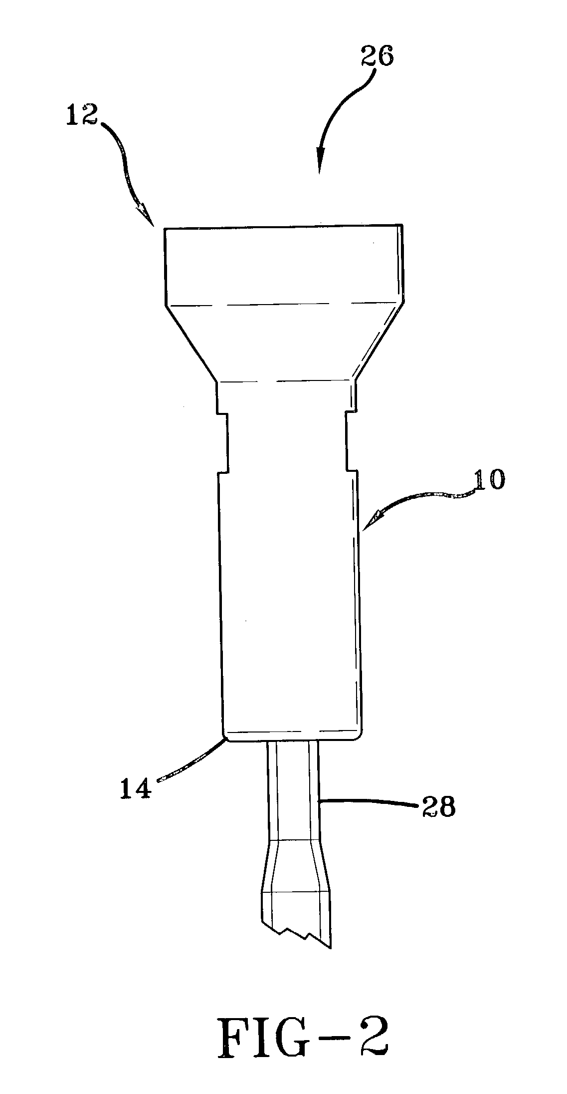
[0048]Referring now to the drawings wherein the showings are for purposes of illustrating at least one embodiment of the invention only and not for purposes of limiting the same, FIGS. 1, 2, and 5 show a new and improved connector 10 for a flexible shaft (not shown), wherein the connector 10 has a drive area 16, an input area 26, a longitudinal axis 78, first end 12, and second end 14. The drive area 16 has a depth 24. The input area 26 has a first end 52, a second end 54, a depth 22, a width 20, and a width 18, with width 20 being measured the first end 52, and the width 18 being measured at the second end 54. The width 20 is wider than the width 18, and wider than the flexible shaft (not shown) for easier insertion of the flexible shaft.

[0049]With continuing reference to FIGS. 1, 2, and 5, the connector 10 is connected to the drive shaft 28 at second end 14. In this embodiment, the width 18 is at least about 0.205 inches, the width 20 is between about 0.372 inches and about 0.654 ...


PUM


Abstract

An improved connector for flex shafts for a string trimmer has an input area and a drive area, where the input area of the connector has a modified diamond shape with sloping sides. This diamond shape allows for easy and reliable connection of the driven working end.

Description

BACKGROUND OF THE INVENTION[0001]A. Field of Invention[0002]This invention pertains to the art of methods and apparatuses for flexible drive shafts for rotary power tools and more particularly to a flexible drive shaft with a connector that allows interchange of driven working ends.[0003]B. Description of the Related Art[0004]Flexible shafts comprise basic elements of power transmission and are designed to transmit power or control from a driving element to an element to be driven. Transmission may be over, under, or around obstacles or objects where transmission by solid shafts would be impractical or impossible.[0005]In a typical rotatable flexible shaft, a wire mandrel has a plurality of layers of closely coiled wire wound thereover, each of the layers being successively wound over another in alternately opposing directions, i.e., right or left-hand lay. This shaft is usually covered by a flexible casing, metallic or covered, and a clearance between the shaft and casing is provid...

Claims


Application Information

Patent Timeline
Patent Type & Authority Patents(United States)
IPC IPC(8): F16B7/00A01D34/416F16C1/08F16D1/10
CPCA01D34/416F16C1/08F16D1/101F16D2001/102Y10T403/63Y10T403/635Y10T403/7098Y10T403/70Y10T403/551
Inventor LOMBARDO, FREDMITCHELL, MICHAEL
Owner MTD PRODUCTS
Why Eureka
Try Eureka