Multi-capillary electrophoresis apparatus

Active Publication Date: 2006-02-28
HITACHI HIGH-TECH CORP
View PDF6 Cites 9 Cited by
  • Summary
  • Abstract
  • Description
  • Claims
  • Application Information

AI Technical Summary

Benefits of technology

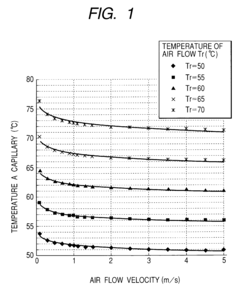
[0026]By using the straightening plate, the air flow formed by the air blowing mechanism and the temperature controlling mechanism provides a prescribed velocity around the capillary array. As a result of the configuration, the difference of the temperatures of the capillaries can be suppressed.

Problems solved by technology

On another front, the amount of Joule heat produced is increased on applying such a high voltage to increase the temperature of the gel, and thus the temperature control becomes further difficult.
Therefore, the region that can be controlled for the temperature thereof is limited to local area.
In the technique disclosed in JP-A-8-297111, only the amount of dispersed heat due to the Joule heat caused by electrophoresis is adjusted, but there is a problem in that temperature control is carried out by providing a heat source for heating.
In the techniques disclosed in JP-A-9-288091 and JP-A-9-251000, there is limitation in increasing the number of capillaries, and the number of samples that can be simultaneously analyzed is limited.
In other words, there is a problem on applying the technique of sandwiching capillaries with plates of plane heat sources to a multi-capillary electrophoresis apparatus that analyzes plural samples at the same time.
However, in the case where more than 12 samples are necessarily analyzed at the same time, or in the case where all the samples set in the microtiter plate having 96 wells are necessarily introduced to a capillary array and subjected to electrophoresis, 12 wells in one row in the microtiter plate are insufficient, and therefore, the samples in several rows or several columns are simultaneously introduced in the capillary array for analysis.
It is impossible in this case to arrange the sampling sections on one plane.
Therefore, it is impossible to employ the technique of sandwiching capillaries with plates of plane heat sources, but it is necessary to carry out temperature control by arranging the capillary array in a steric space, such as a thermostat oven.
Therefore, there is such a problem upon using the ordinary air circulation thermostat oven that the temperature of the capillaries is differentiated with respect to the positions.
Therefore, it cannot provide a uniform air flow velocity distribution in the thermostat oven for forming a uniform temperature distribution by forced convection.
Therefore, the radiation heat from the plates having good thermal conduction is insufficient in the plane air circulation method, and thus there is a problem in that the temperature difference occurs with respect to the positions.

Method used


Image

  • Multi-capillary electrophoresis apparatus
  • Multi-capillary electrophoresis apparatus
  • Multi-capillary electrophoresis apparatus

Examples


first embodiment

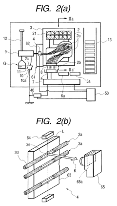
[0046]Based on the foregoing discussion, an electrophoresis apparatus according to the invention will be described below with reference to FIGS. 2A to 6B and 8 to 9B. FIG. 2A is a diagram showing a structure of a capillary electrophoresis apparatus for DNA sequencing, and FIG. 2B is a diagram showing a schematic structure of a detector part for analyzing a sample. FIGS. 3A to 3C are diagrams showing structures of air thermostat ovens in the capillary electrophoresis apparatus for DNA sequencing shown in FIG. 2A, and FIG. 3A is a side cross sectional view on line IIa–IIa′ in FIG. 2A. FIG. 3B is a front elevational view of the air thermostat oven, and FIG. 3C is a diagram showing a modified example of the air thermostat oven shown in FIG. 3A. FIG. 4A is a perspective view showing a fan used in the air thermostat oven and an air circulation channel, FIG. 4B is a perspective view showing a modified example of the fan, and FIG. 4C is a side elevational view showing the fan shown in FIG. ...

second embodiment

[0113]A multi-capillary electrophoresis apparatus according to the invention and a modified example thereof will be described with reference to FIGS. 10A and 10B.

[0114]FIG. 10A is a diagram showing the structures of the chamber part 29, 30 and the capillary housing base 28 of the multi-capillary electrophoresis apparatus according to the second embodiment of the invention. Detailed descriptions of the other constitutional elements thereof are omitted herein because they are similar to those for the multi-capillary electrophoresis apparatus according to the first embodiment of the invention.

[0115]The arrows in the figures denote the direction of the air flow. A first straightening plate 24 can change the air flow in parallel to the first straightening plate 24 in the chamber part 29, 30 to the air flow perpendicular thereto. The first straightening plate 24 can also form an air flow having a uniform flow direction without formation of vortex flow in the capillary housing base 28. The...


PUM

PropertyMeasurementUnit
Fractionaaaaaaaaaa
Fractionaaaaaaaaaa
Fractionaaaaaaaaaa

Abstract

Scattering on analysis in a multi-capillary electrophoresis apparatus is suppressed. The multi-capillary electrophoresis apparatus has a multi-capillary array that has a sample and a separation medium for separating a sample charged therein, and has a sampling section formed at ends of the capillaries and a detector part for acquiring information depending on the sample thus separated, a means for applying a voltage between the sampling section and the detector part, a chamber part having an air blowing mechanism and a temperature controlling mechanism, a capillary housing base provided on a leeward side of the air blowing mechanism and housing the multi-capillary array, and a first straightening plate provided between the chamber part and the capillary housing base.

Description

BACKGROUND OF THE INVENTION[0001]1. Field of the Invention[0002]The present invention relates to an electrophoresis apparatus capable of separating components in a sample by electrophoresis, and more particularly, it relates to a multi-capillary electrophoresis apparatus having plural capillaries.[0003]2. Description of the Related Art[0004]DNA sequencing has been conventionally carried out by a slab gel method, in which a gel for separating a sample is sandwiched with two sheets of transparent glass plate, and a voltage is applied to both ends of the glass plates to effect electrophoresis. JP-A-7-301619, JP-A-8-297111 and JP-A-9-288091 disclose techniques for uniformly maintaining the temperature of the gel within the slab.[0005]An electrophoresis apparatus of the slab gel method disclosed in JP-A-7-301619 has two sheets of transparent glass plates with a thermal control plate, a Peltier element attached in contact with the back surface thereof, a heat sink attached to the heat dis...

Claims


Application Information

Patent Timeline
IPC IPC(8): G01N27/453G01N33/483C12M1/00C12M1/34G01N27/447
CPCG01N27/44782G01N27/44708
InventorYAMAZAKI, MOTOHIROKOJIMA, MASAYAINABA, RYOJI
OwnerHITACHI HIGH-TECH CORP