
Device for storing liquids

a technology for liquid storage and containers, applied in the direction of rigid containers, containers, packaging, etc., can solve the problems of high transportation costs, large volume of large containers, and large volume of large containers, and achieve the effect of inexpensive shipping

Inactive Publication Date: 2006-03-07
RICHTER BODO
View PDF8 Cites 3 Cited by
  • Summary
  • Abstract
  • Description
  • Claims
  • Application Information

AI Technical Summary

Benefits of technology

[0006]Therefore, the goal of the invention is to develop a device for storing liquids, which, on the one hand, can be economocally manufactured by using inexpensive molds and, on the other hand, can also be inexpensively shipped from the manufacturing site to the storage site.
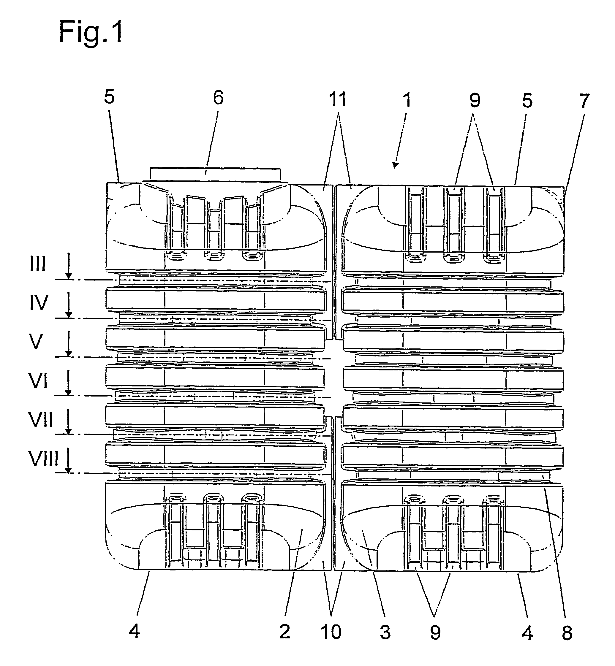
[0008]The individual container parts of the device for storing liquids can be manufactured inexpensively with production systems whose production or blowing volume is considerably smaller than the desired storage volume. The lines that were previously necessary between the individual container parts for filling, emptying, and venting the containers can be eliminated.

Problems solved by technology

However, blow-molded plastic containers are limited in their size.
This is related to the fact that very large containers require large and thus expensive blow molds.
Moreover, high transportation costs are associated with very large containers.
Despite this interconnection of the individual containers, there is always the danger that the individual containers cannot be uniformly filled and uniformly or completely emptied.

Method used


Image

  • Device for storing liquids
  • Device for storing liquids
  • Device for storing liquids

Examples


Embodiment Construction

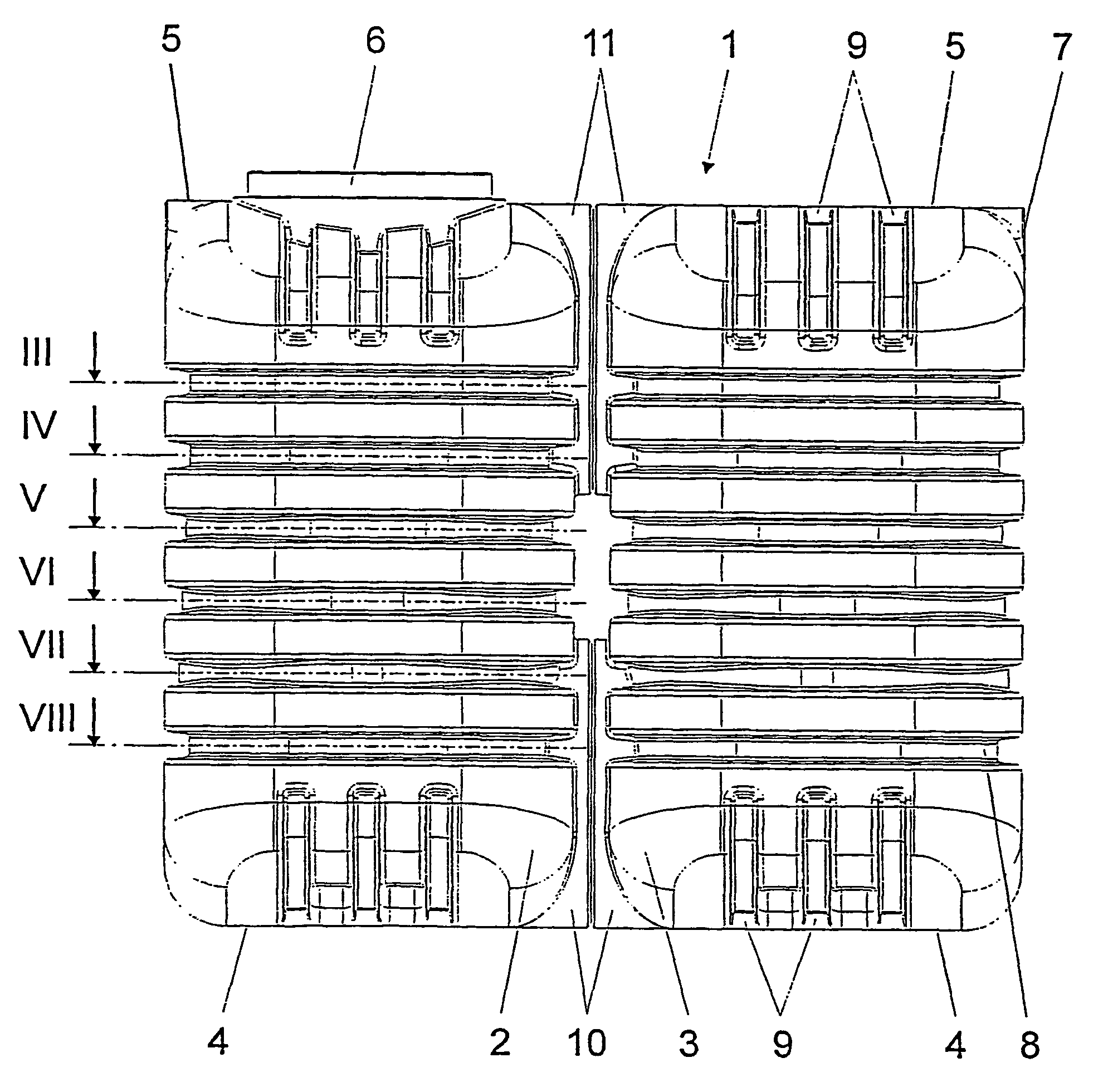
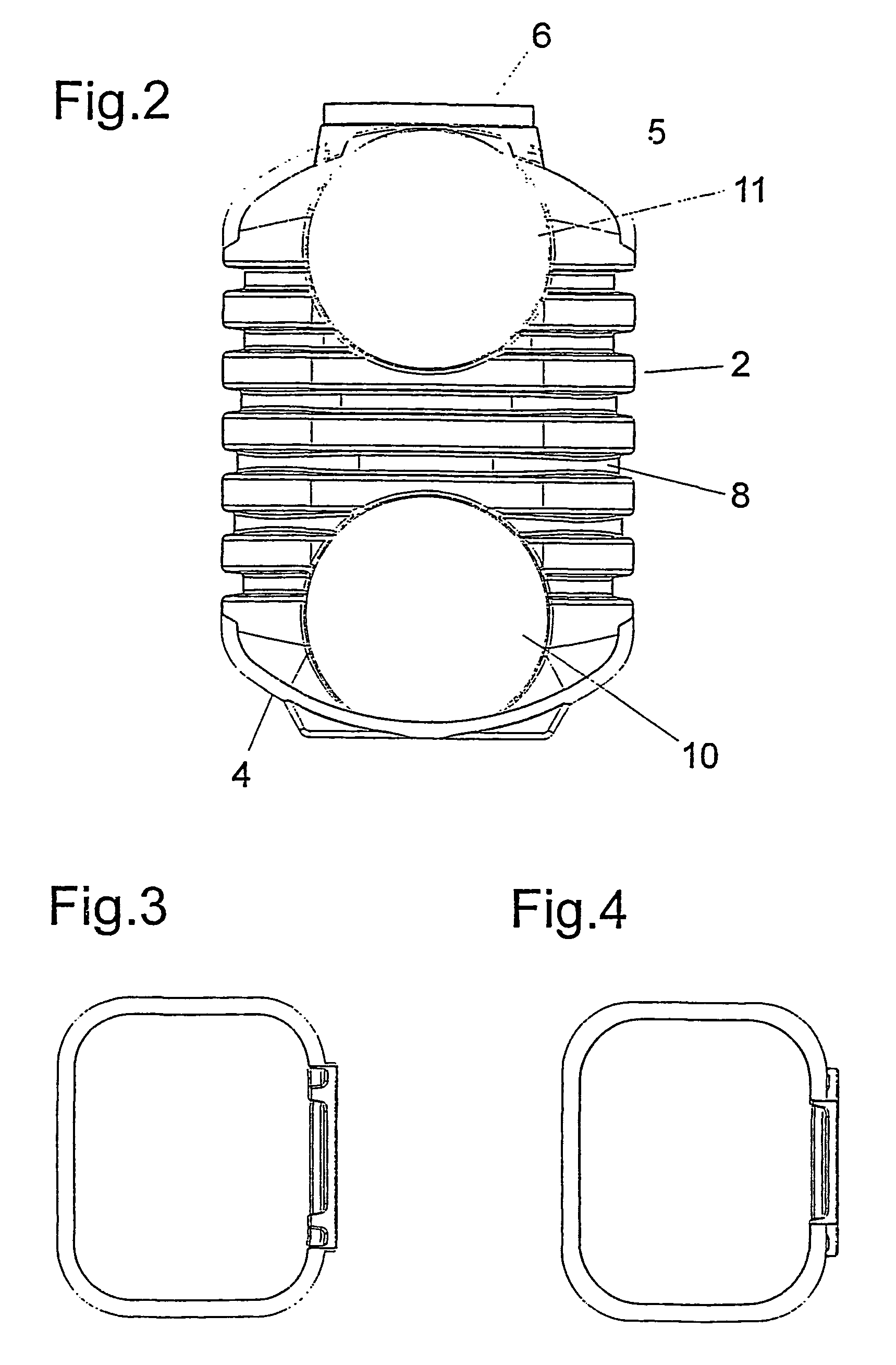
[0015]FIG. 1 shows a device for storing liquids, which, in this embodiment, consists of a container 1 that is composed of two container parts 2, 3. Both container parts 2, 3 are made of plastic, for example, high-molecular-weight high-density polyethylene, and are produced by blow molding. They have an approximately rectangular cross section. Each container part 1, 2 has an underside 4 and an upper side 5 and, in the embodiment shown here, has a height that is about twice as great as the largest cross-sectional dimension. This means that the two container parts 2, 3 have an essentially rectangular-solid shape. The two container parts 2, 3 are advantageously produced in the same blow-molding mold; a different mold insert must be present only in the upper region of this mold. This is related to the fact that the upper region of container part 2 has a socket 6 with an opening, through which the container 1 can be filled and emptied.

[0016]In the middle section of both container parts 2,...


PUM


Abstract

The invention relates to a device for storing liquids comprised of a plastic container, which is produced by a blowing process, which has a single layer or multilayer wall, and which is provided with at least one filling and emptying opening. The aim of the invention is, on the one hand, to economically manufacture a device of the aforementioned type by using inexpensive forming tools and, on the other hand, to be able to transport the device from the production site to the storing site also without incurring large expenditures. To this end, the container (1) is formed from at least two separately manufactured and largely identical container parts (2, 3), each of which comprising an approximately rectangular cross section with an underside (4) and a upper side (5) and having a height that is considerably greater than the largest cross section measure. Each of the container parts also have, on one side, a lower and an upper flow socket (10, 11), and are joined to one another in the area of these flow sockets (10,11) whereby forming one piece.

Description

BACKGROUND OF THE INVENTION[0001]1. Field of the Invention[0002]The invention concerns a device for storing liquids, which consists of a plastic container produced by a blowing process, has a single-layer or multilayer wall, and is provided with at least one filling and emptying hole.[0003]2. Description of the Related Art[0004]To hold liquids, especially rainwater and wastewater, devices are used, which consist of a plastic container, which is often installed underground or buried in the ground. Plastic containers of this type are produced mainly by rotational molding with the use of glass fibers or by blow molding. Mainly high-molecular-weight high-density polyethylene, which not only is inexpensive, but also can be easily processed and is highly durable, is used for containers produced by blow molding. However, blow-molded plastic containers are limited in their size. This is related to the fact that very large containers require large and thus expensive blow molds. Moreover, hig...

Claims


Application Information

Patent Timeline
Patent Type & Authority Patents(United States)
IPC IPC(8): B65D79/00B65D6/02B65D8/12B65D88/02B65D88/06B65D88/76
CPCB65D88/022B65D88/76B65D88/06
Inventor RICHTER, GUNTER
Owner RICHTER BODO
Learn More