Hydraulically activated swivel for running expandable components with tailpipe

a technology of hydraulic activation and expandable components, which is applied in the direction of hose connections, wellbore/well accessories, ways, etc., can solve the problems of swivel not allowing the running assembly to act as one rotationally locked unit, enlarge the path through which both fluid and downhole tools may travel, and increase the likelihood of encountering a downhole obstruction

Inactive Publication Date: 2006-03-14
WEATHERFORD TECH HLDG LLC
View PDF24 Cites 57 Cited by
  • Summary
  • Abstract
  • Description
  • Claims
  • Application Information

AI Technical Summary

Benefits of technology

[0014]A hydraulically activated swivel for use in a well is also provided. The hydraulically activated swivel consists of an upper tubular and a lower tubular. The lower tubular is connected to a bottom connection by a lower spline assembly. The hydraulically activated swivel further includes a sleeve member connected to the upper tubular. The sleeve member movable from a first location to a second location. In the first location, the lower spline assembly is fully engaged, thereby permitting the upper and lower tubular to rotate as one unit. While in the second location, the lower spline assembly is disengaged, thereby allowing the upper tubular to rotate independent of the lower tubular in a first direction and with the lower tubular in a second direction.

Problems solved by technology

This, in turn, enlarges the path through which both fluid and downhole tools may travel.
Several problems may occur using a conventional swivel and the running assembly to expand a liner downhole.
One problem particularly associated with running the liner into the wellbore is the likelihood of encountering a downhole obstruction.
However, the conventional swivel does not permit the running assembly to act as one rotationally locked unit.
Another problem is associated with the removal of the running tool from the liner after the expansion operation.
When the running tool primary release mechanism fails to operate properly, it may be necessary to rotate the running tool to the left to mechanically disconnect the running tool from the liner.
However, the conventional swivel does not have the functionality to release the running tool by rotating the swivel in a single direction.

Method used


Image

  • Hydraulically activated swivel for running expandable components with tailpipe
  • Hydraulically activated swivel for running expandable components with tailpipe
  • Hydraulically activated swivel for running expandable components with tailpipe

Examples


Embodiment Construction

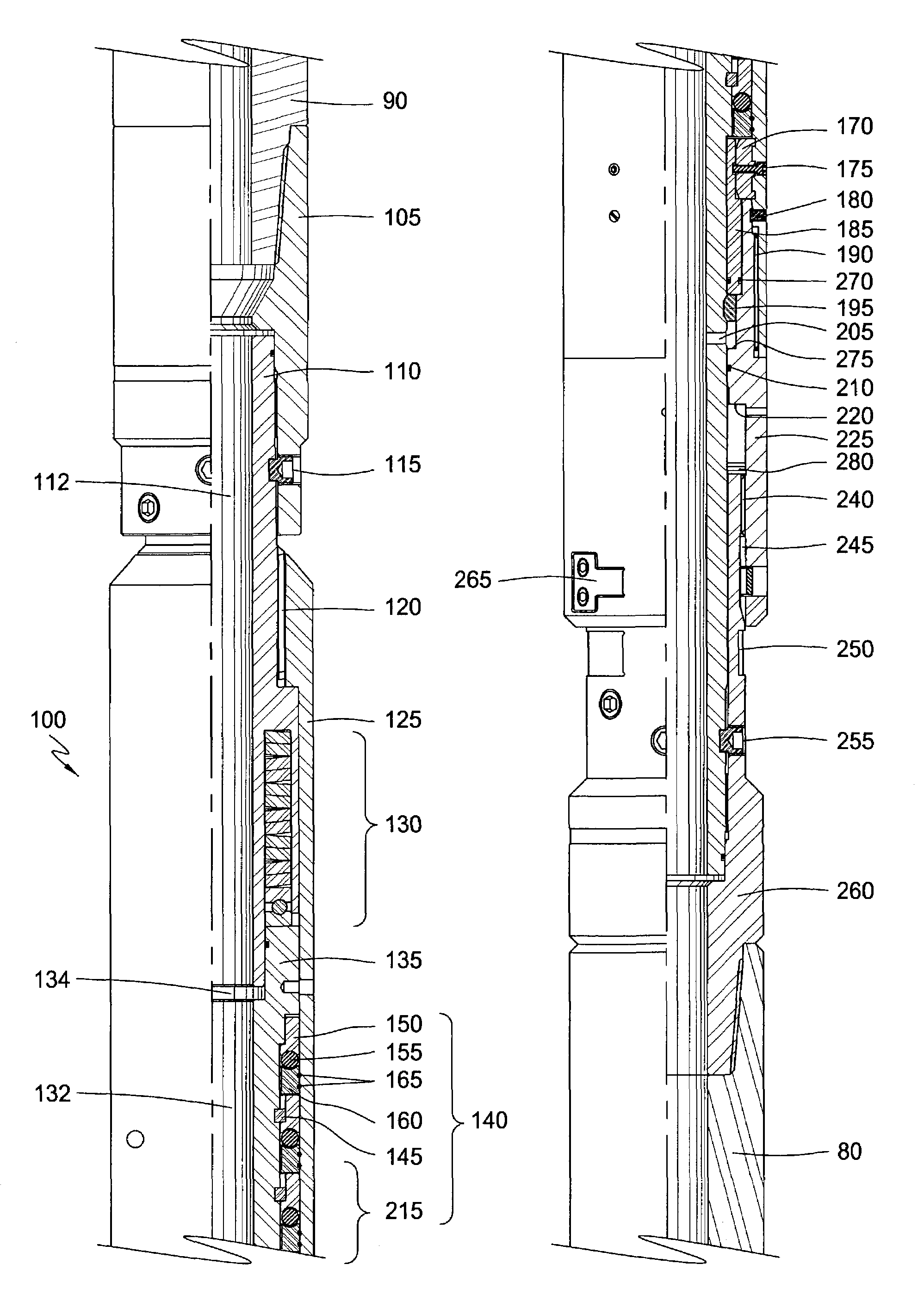
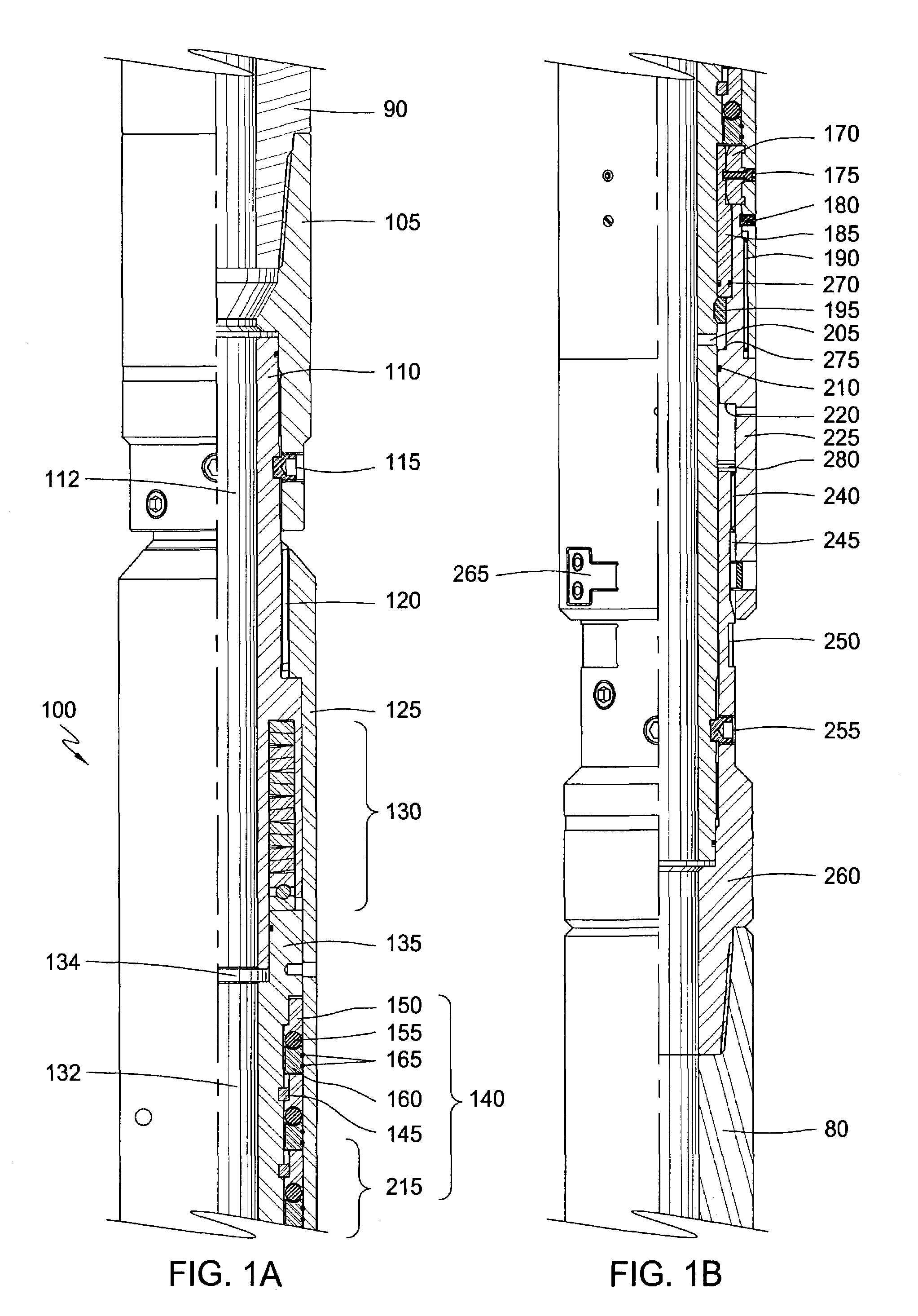
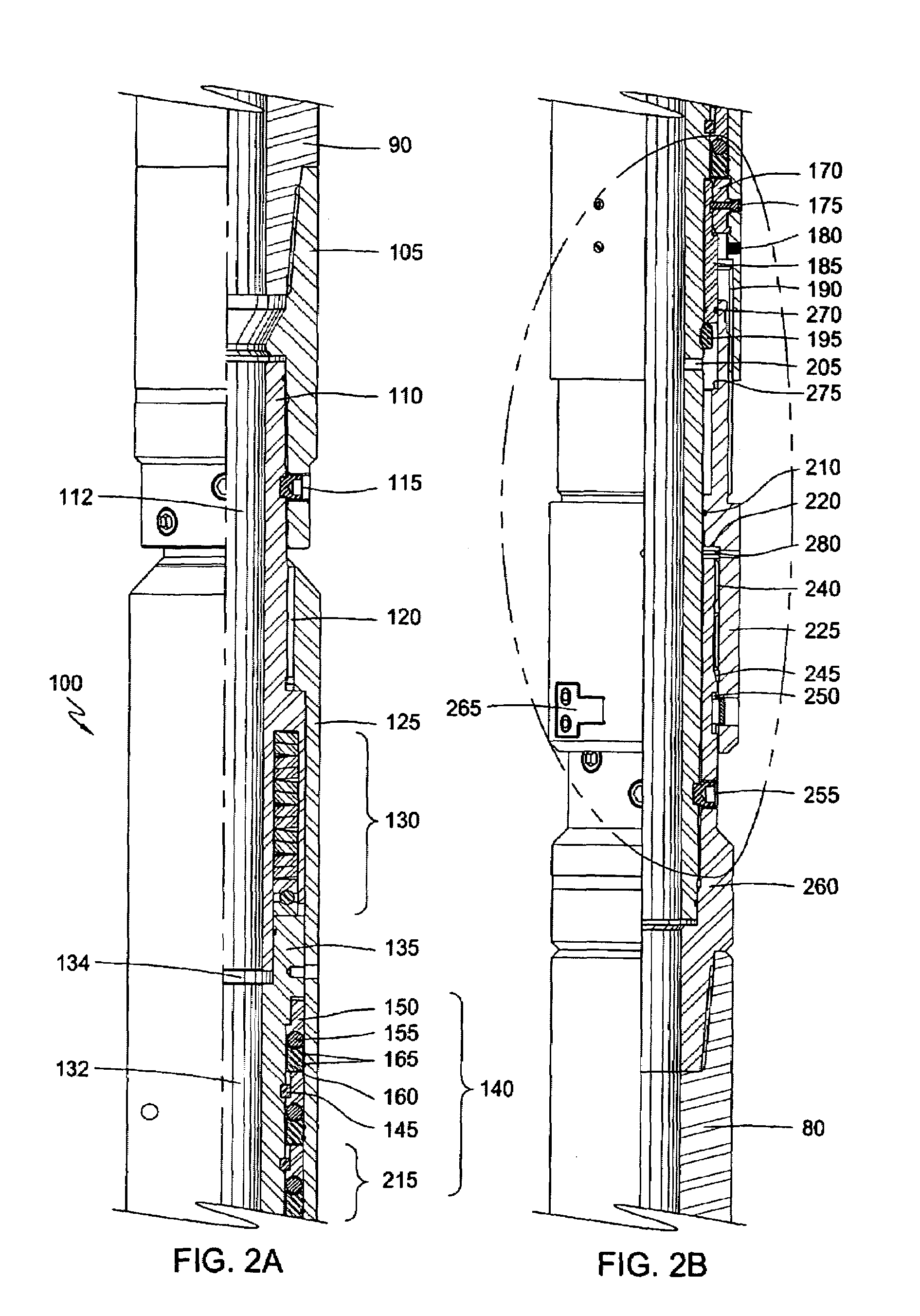
[0022]This invention comprises of a hydraulically activated swivel 100 useful in a running assembly to expand an expandable liner downhole. Generally, the expandable liner is a tubular or tailpipe that is anchored or suspended at the bottom of the previous tubular string. Typically, the expandable liner is anchored or suspended by expanding an upper portion of the expandable liner into frictional contact with a lower portion of the tubular string. The expandable liner may be constructed and arranged to apply to various downhole applications.

[0023]In one application, the expandable liner may be constructed to include an integral packer arrangement to seal and hang the expandable liner from the previous tubular string. In the integral packing arrangement, the body of the expandable liner is modified by machining grooves into the surface. Thereafter, the grooves are typically filled with a pliable material, such as an elastomer, forming a packer, thereby increasing the sealing capabili...


PUM


Abstract

An apparatus for use in a wellbore, the apparatus comprises a top body, a bottom body, and a sleeve mechanically connected to the top and bottom bodies. The sleeve movable between a first position to a second position, whereby in the first position, the top and bottom bodies rotate as one unit and in the second position, the top body rotates independent of the bottom body in a first direction and with the bottom body in a second direction. A method for completing a wellbore, wherein the method comprises running an assembly and a liner disposed on a drill string into the wellbore. The assembly includes an expander tool, a hydraulically actuated swivel, and a running tool mechanically connected to the liner. The method includes rotating the assembly and the liner as one rotationally locked unit. The method further includes activating the expander tool, expanding the liner into the existing casing, deactivating the expander, and then removing the drill string and running assembly from the wellbore.

Description

BACKGROUND OF THE INVENTION[0001]1. Field of the Invention[0002]The present invention generally relates to an apparatus and methods for wellbore completion. More particularly, the invention relates to an apparatus and methods for allowing rotational movement of downhole tools. More particularly yet, the invention provides a hydraulically activated swivel.[0003]2. Description of the Related Art[0004]In the drilling of oil and gas wells, a wellbore is formed using a drill bit that is urged downwardly at a lower end of a drill string. After drilling a predetermined depth, the drill string and bit are removed, and the wellbore is lined with a string of steel pipe called casing. The casing provides support to the wellbore and facilitates the isolation of certain areas of the wellbore adjacent hydrocarbon bearing formations. The casing typically extends down the wellbore from the surface of the well to a designated depth. An annular area is thus defined between the outside of the casing a...

Claims


Application Information

Patent Timeline
Patent Type & Authority Patents(United States)
IPC IPC(8): E21B17/05E21B17/02E21B43/10
CPCE21B17/05E21B43/103Y10T403/11F16B2200/63E21B43/10
Inventor MAGUIRE, PATRICK G.
Owner WEATHERFORD TECH HLDG LLC
Why Eureka
Try Eureka