Rod guide and seal system for gas filled shock absorbers

a gas-filled shock absorber and rod guide technology, which is applied in the direction of shock absorbers, springs/dampers, vibration dampers, etc., can solve the problems of variable damping force of shock absorbers, difficulty in making them sensitive to vibration frequency,

Active Publication Date: 2006-03-14
TENNECO AUTOMOTIVE OPERATING CO INC
View PDF21 Cites 37 Cited by
  • Summary
  • Abstract
  • Description
  • Claims
  • Application Information

AI Technical Summary

Benefits of technology

[0008]Further areas of applicability of the present invention will become apparent from the detailed description provided hereinafter. It should be understood that the detailed description and specific examples, while indicating the preferred embodiment of the invention, are intended for purposes of illustration only and are not intended to limit the scope of the invention.

Problems solved by technology

While meeting with success in the automotive industry, hydraulic liquid filled shock absorbers are not without their problems.
One problem with these prior art shock absorbers is the difficulty to make them sensitive to the frequency of the vibrations.
Other problems associated with the prior art hydraulic liquid filled shock absorbers include the variability in their damping forces due to the temperature changes of the hydraulic liquid.
In addition, any aeration of the hydraulic liquid during operation adversely affects the operation of the damper due to the introduction of a compressible gas into a non-compressible hydraulic liquid.
Finally, the hydraulic liquid adds to the weight of the shock absorber as well as presenting environmental concerns regarding the use of a hydraulic liquid.
While gas filled shock absorbers have addressed some of the problems associated with hydraulic liquid dampers, they are not without their own unique problems.
One area that presents problems for the gas filled shock absorbers is the sealing system incorporated into the rod guide assembly which seals and lubricates the piston rod.
A problem with this prior art design is that the pressure in the oil chamber can increase over time.
Such a pressure raise causes an increase in the amount of seal friction and thus the accelerated wear of the seals.

Method used


Image

  • Rod guide and seal system for gas filled shock absorbers
  • Rod guide and seal system for gas filled shock absorbers
  • Rod guide and seal system for gas filled shock absorbers

Examples


Embodiment Construction

[0017]The following description of the preferred embodiment(s) is merely exemplary in nature and is in no way intended to limit the invention, its application, or uses.

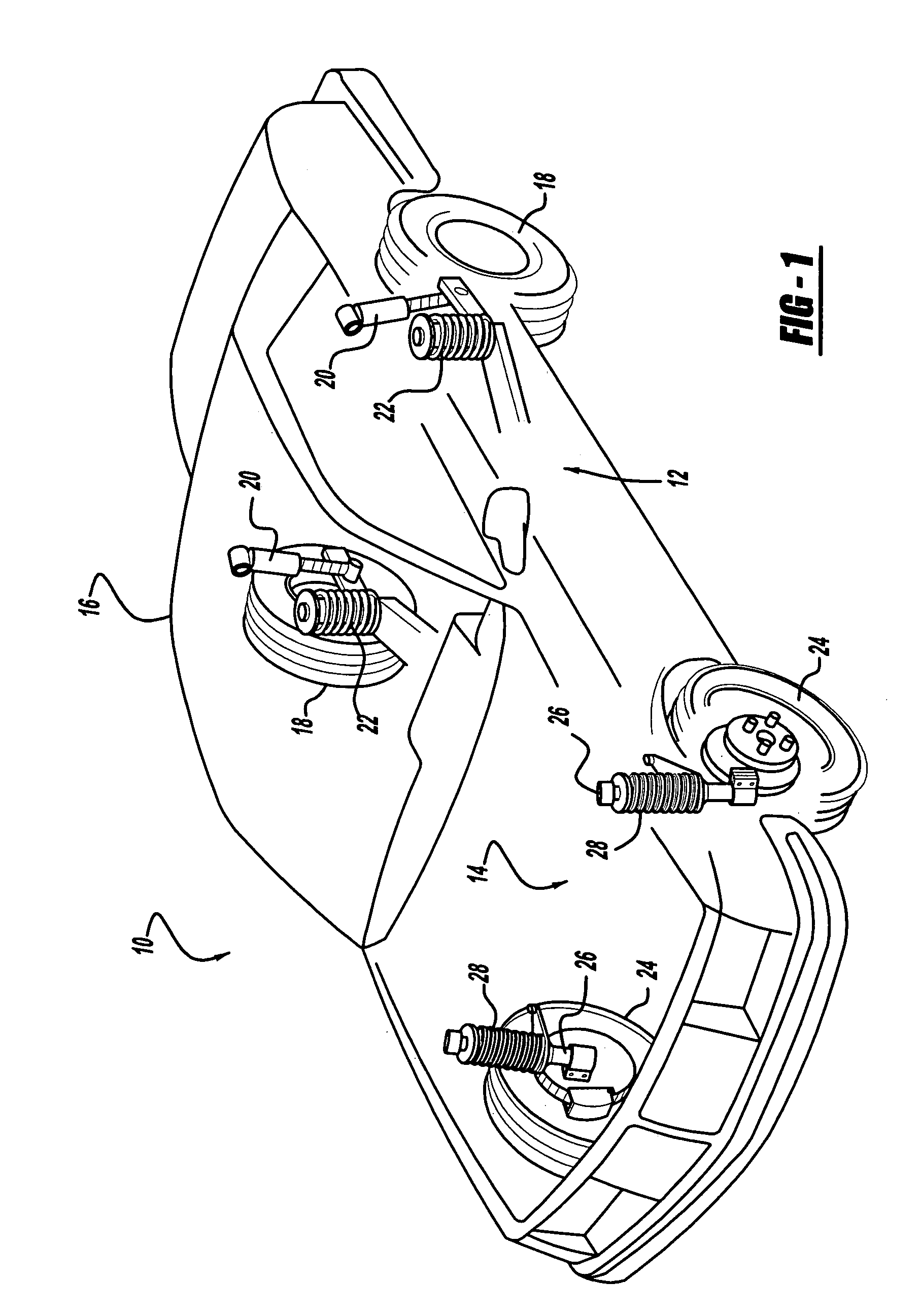
[0018]Referring now to the drawings in which like reference numerals designate like or corresponding parts throughout the several views, there is shown in FIG. 1 a vehicle incorporating a suspension system having the frequency dependant dampers in accordance with the present invention which is designated generally by the reference numeral 10. Vehicle 10 includes a rear suspension system 12, a front suspension system 14 and a body 16. Rear suspension system 12 includes a pair of independent suspensions adapted to operatively support a pair of rear wheels 18. Each rear independent suspension is attached to body 16 by means of a shock absorber 20 and a helical coil spring 22. Similarly, front suspension 14 includes a pair of independent suspensions adapted to operatively support a pair of front wheels 24. Each independen...


PUM


Abstract

A gas shock absorber has a pressure tube which defines a working chamber. A piston assembly divides the working chamber into an upper working chamber and a lower working chamber. A plurality of extension passages extend through the piston assembly and are opened and closed by an extension valve assembly. A plurality of compression passages extend through the piston assembly and are opened and closed by a compression valve assembly. A rod guide assembly is located between the pressure tube and the piston rod. The rod guide assembly includes an oil chamber for sealing and lubricating the piston rod. An axially movable piston maintains the pressure within the oil chamber equal to the pressure in the upper working chamber.

Description

FIELD OF THE INVENTION[0001]The present invention relates generally to dampers and shock absorbers adapted for use in a suspension system such as the suspension system used for automotive vehicles. More particularly, the present invention relates to a rod guide assembly for a shock absorber which utilizes a gas rather than a hydraulic liquid as the damping medium.BACKGROUND OF THE INVENTION[0002]Shock absorbers are used in conjunction with automotive suspension systems to absorb unwanted vibrations which occur during driving. To absorb the unwanted vibrations, shock absorbers are generally connected between the sprung portion (body) and the unsprung portion (suspension) of the automobile. A piston is located within a pressure tube of the shock absorber and the pressure tube is normally attached to the unsprung portion of the vehicle. The piston is normally attached to the sprung portion of the vehicle through a piston rod which extends through the pressure tube. The piston divides t...

Claims


Application Information

Patent Timeline
Patent Type & Authority Patents(United States)
IPC IPC(8): F16F9/36F16F9/34
CPCF16F9/3405F16F9/365F16F9/362F16F9/36
Inventor LEMMENS, ROBBYDE MAESSCHALCK, TOMVERDEYEN, DIRKBOON, PETER
Owner TENNECO AUTOMOTIVE OPERATING CO INC
Why Eureka
Try Eureka