
Method of anti-blinding for active night vision system

a night vision system and active technology, applied in the field of night vision systems, can solve problems such as blindness in vision systems, and achieve the effect of mitigating the blinding effect of nearby

Inactive Publication Date: 2006-03-14
FORD GLOBAL TECH LLC
View PDF13 Cites 11 Cited by
  • Summary
  • Abstract
  • Description
  • Claims
  • Application Information

AI Technical Summary

Benefits of technology

The present invention provides an active night vision system for vehicles that reduces the blinding effects of nearby vehicles with similar night vision systems. The system includes a light source and a light sensor to detect the presence of another vehicle's night vision system. The controller shifts the pulses from the first night vision system in a different direction than the pulses from the second vehicle's system until they annihilate each other, reducing the blinding effect on the first system. This technology ensures safe driving at night and improves overall safety for drivers and passengers.

Problems solved by technology

A problem encountered by night vision systems is blinding, wherein two vehicle including night vision systems approach each other.

Method used


Image

  • Method of anti-blinding for active night vision system
  • Method of anti-blinding for active night vision system
  • Method of anti-blinding for active night vision system

Examples


first embodiment

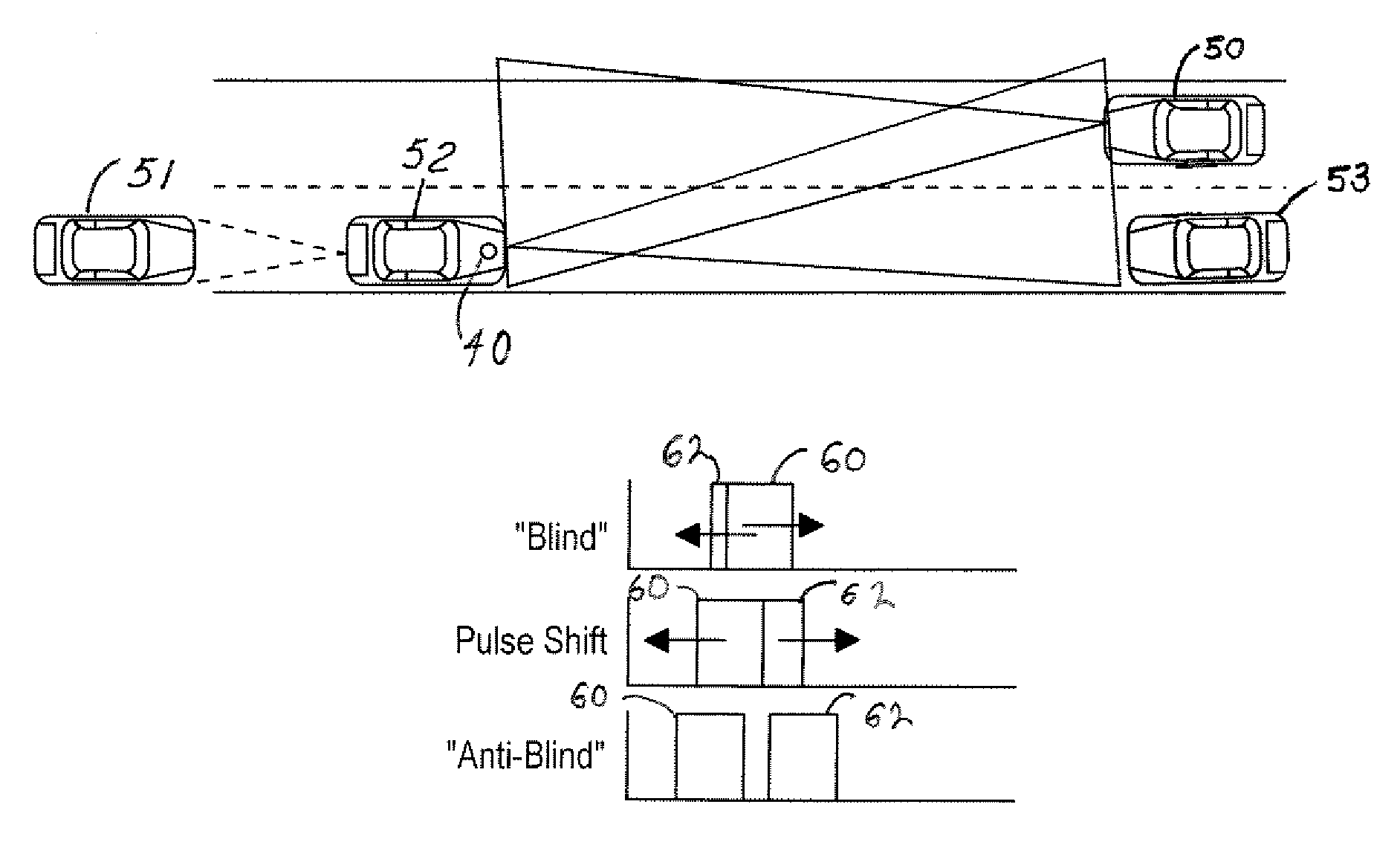
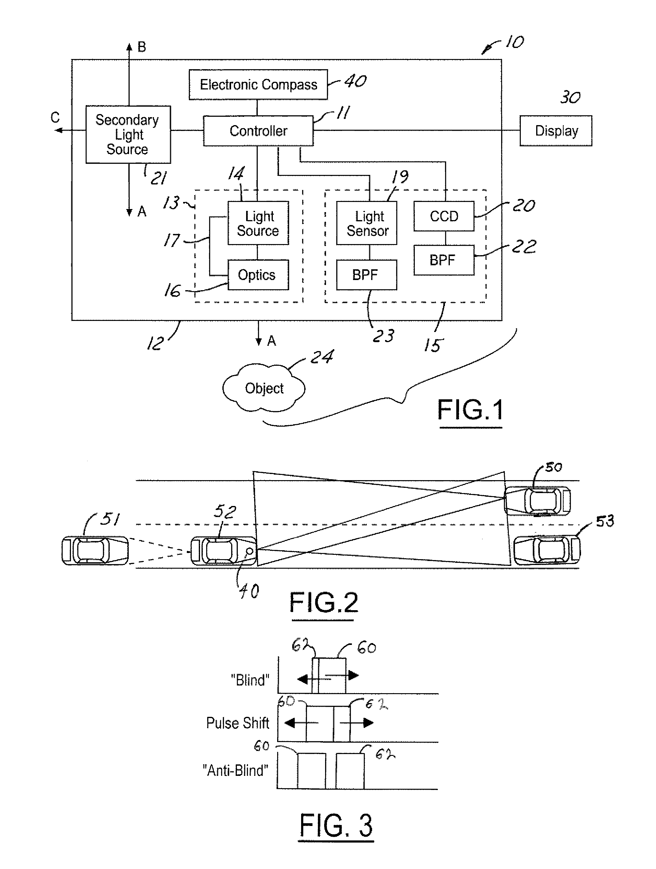
[0039]Referring now to FIG. 3, there is shown an anti-blinding scheme illustrating the night vision signals for the vehicles 50, 52 of FIG. 2 in accordance with the present invention.

[0040]Illustrated are pulse phases 60 and 62 from the vehicle 52 and the vehicle 50. For the present embodiment, all vehicles are equipped with NV systems.

[0041]The controller 11 of the vehicle 52 receives detected opposing IR light and shifts the pulse phase of that opposing light to the right. Resultantly, the pulse phase shifts in small increments until blinding is prevented. A controller within vehicle 50 may also shift opposing signals, thereby accelerating the process. Alternately, if the vehicle 51 is following the vehicle 52, and both are equipped with NV, the system modifies the pulse pattern in real-time, as was discussed above.

second embodiment

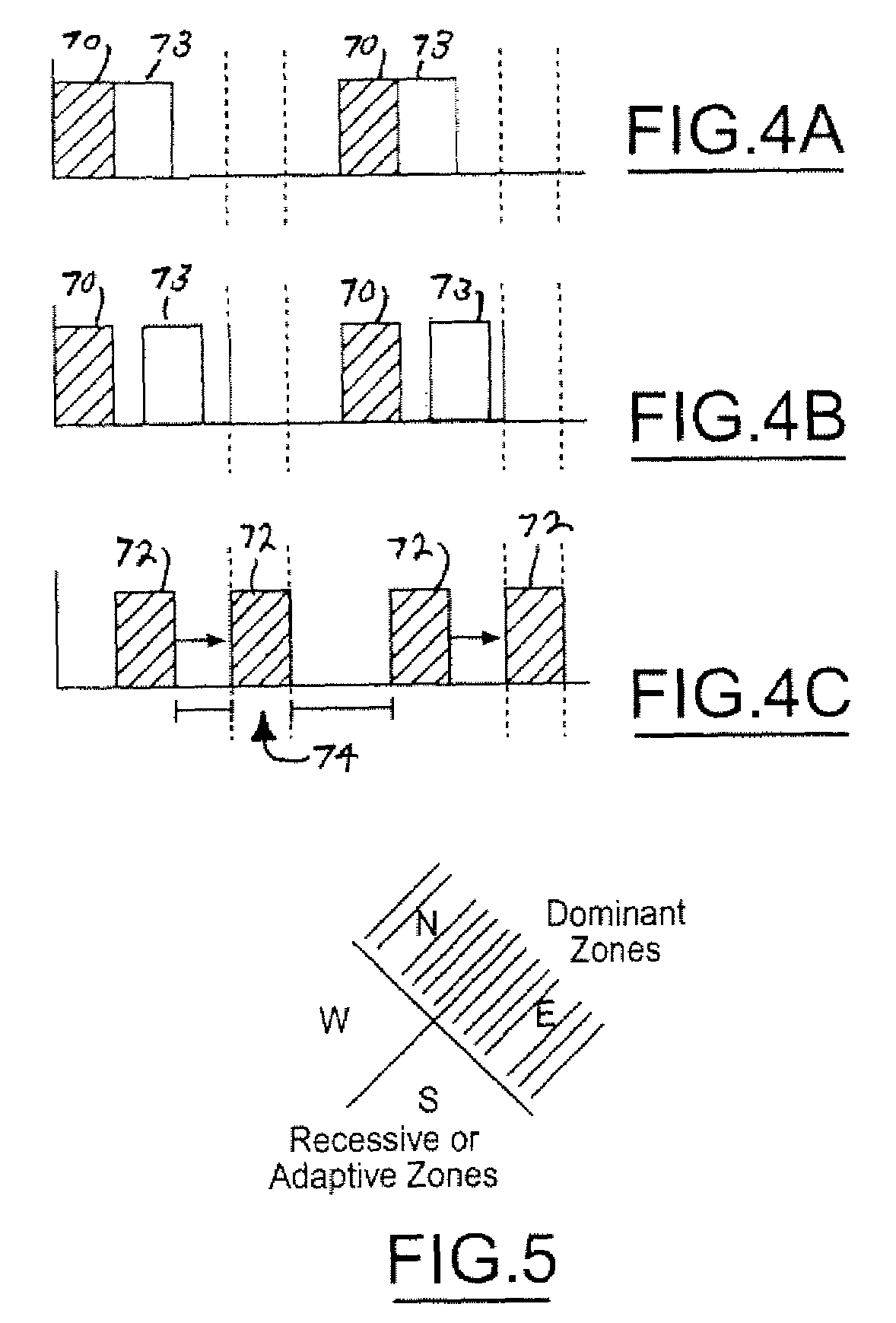
[0042]Referring now to FIGS. 4a, 4b, and 4c, there is shown an anti-blinding scheme illustrating the night vision signals for the vehicles 50, 52 of FIG. 2 in accordance with the present invention.

[0043]Illustrated in FIG. 4(a) are dominant pulse phases 70 from vehicle 50 and dominant pulse phases 73 from vehicle 53 traveling alongside vehicle 50. Illustrated in FIG. 4(b) are shifted pulse phases 70 and 73. Illustrated in FIG. 4(c) are pulse phases 72 from adaptive vehicle 52 shifted into an optimized position to avoid blinding. For illustration, all vehicles are equipped with NV systems, and the vehicle 52 further includes an electronic compass 40.

[0044]The compass 40 is broken into zones, e.g. N (315–45 deg), E (45–135 deg), S (135–225 deg), and W (225–315 deg). This generates four zones where half are deemed dominant, their pulse pattern will be the signal that the other adaptive zones will use to modify their pulse pattern to avoid blinding or pulse overlap.

[0045]For a dominant ...


PUM


Abstract

A night vision system for a vehicle includes a first light source for illuminating a region proximate the vehicle, the light source generating a first night vision pulse signal. The system further includes a light sensor receiving a second night vision pulse signal from an approaching vehicle, wherein the second night vision pulse blinds the first night vision pulse signal. A controller shifts pulses from the first night vision pulse signal in a different direction than pulses from the second night vision pulse signal until an anti-blinding of the first night vision pulse signal by the second night vision pulse signal is achieved.

Description

BACKGROUND OF INVENTION[0001]The present invention relates to a night vision system for detecting objects at relatively low visible light levels. In particular, the invention concerns an active night vision system having an anti-blinding scheme employing pulsed illumination and synchronization with detected pulsed light sources from approaching vehicles.[0002]Night vision systems are utilized to allow a user to see objects at relatively low visibility light levels. Night vision systems are typically classified as either passive night vision systems or active night vision systems. In known passive night vision systems used in automotive applications, mid-infrared cameras are used to image objects using the ambient infrared light emitted by the objects in the environment.[0003]Known active night vision systems utilize a near-infrared (NIR) laser diode or a filtered incandescent light source to generate NIR light. The NIR light is subsequently reflected off objects in the environment a...

Claims


Application Information

Patent Timeline
Patent Type & Authority Patents(United States)
IPC IPC(8): G08G1/01B60Q1/02B60Q1/00B60R1/00G02B23/12G08G1/16H04N7/18
CPCB60R1/00G02B23/12B60R2300/103B60R2300/50B60R2300/8066B60R2300/106B60R1/23B60R1/30
Inventor SHAFFER, ARIC DAVID
Owner FORD GLOBAL TECH LLC
Learn More