Image forming apparatus with control adjusting bias output based on recording material surface roughness

a technology bias output, which is applied in the direction of electrographic process apparatus, instruments, optics, etc., can solve the problems of insufficient transfer of image forming apparatus to cardboard material, inability to completely overcome the above-described art transfer defects, etc., and achieve the effect of improving the transfer stability

Active Publication Date: 2006-03-14
CANON KK
View PDF5 Cites 16 Cited by
  • Summary
  • Abstract
  • Description
  • Claims
  • Application Information

AI Technical Summary

Benefits of technology

[0011]It is an object of the present invention to provide an image forming apparatus with improved transfer stability irrespective of the surface roughness of a transfer medium.

Problems solved by technology

However, such an image forming apparatus has a problem of being incapable of sufficient transfer to a cardboard material having a surface with bumps and dips provided thereon, such as embossed paper or debossed paper.
However, the above-described art does not completely overcome transfer defects due to surface roughness.
The occurrence of a transfer failure due to surface roughness is attributable to a phenomenon that, when a transfer current is applied in a state where a toner image on an intermediate transfer member and a recording material are not sufficiently adhered to each other, an abnormal electric discharge occurs in a gap between the toner image and the recording material, thereby hindering the toner from being normally transferred.
Therefore, simply changing a method for applying a transfer electric field provides no basic solution to the problem.

Method used


Image

  • Image forming apparatus with control adjusting bias output based on recording material surface roughness
  • Image forming apparatus with control adjusting bias output based on recording material surface roughness
  • Image forming apparatus with control adjusting bias output based on recording material surface roughness

Examples


first embodiment

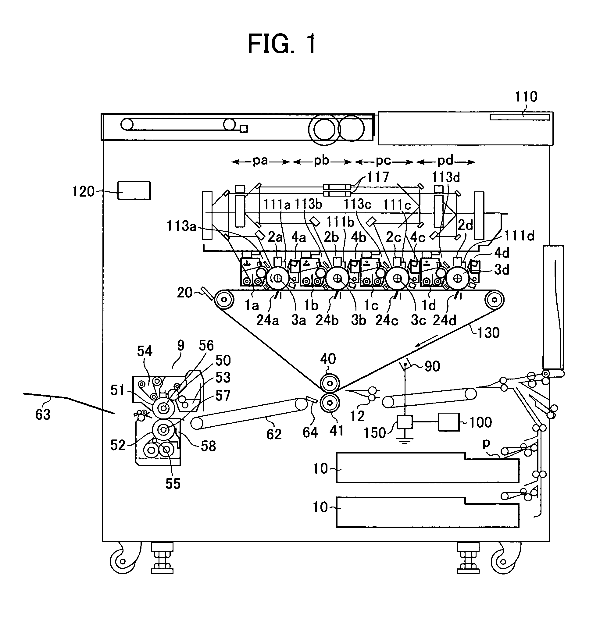
[0024]FIG. 1 shows an example of an image forming apparatus according to a first embodiment of the present invention.

[0025]The image forming apparatus shown in FIG. 1 is a full color laser printer with four colors. This image forming apparatus includes an intermediate transfer belt 130 serving as an intermediate transfer member on which toner images are once superimposed on one another; four image forming sections sequentially disposed from the upstream side along its moving direction (i.e., the direction indicated by the arrow along this belt in FIG. 1), which comprises a first “yellow” image forming section Pa, a second “magenta” image forming section Pb, a third “cyan” image forming section Pc, and a fourth “black” image forming section Pd.

[0026]The first to fourth image forming sections Pa, Pb, Pc, and Pd, respectively, have their exclusive image carriers, which are, in the first embodiment, drum type electrographic photoconductors (hereinafter referred to as “photoconductive dr...

second embodiment

[0055]In a second embodiment of the present invention, as its basic construction, the electrographic type image forming apparatus used in the above-described first embodiment, is employed.

[0056]This embodiment is characterized in that, in order to change the toner tribo before the second transfer, the toner tribo before the first transfer is changed by electrifiers 45a to 45d each provided on the respective drums as shown in FIG. 3. FIG. 3 illustrates one portion of the image forming apparatus described in the first embodiment, the portion having the same construction as that of the first embodiment except for the addition of electrifiers 45a to 45d. In FIG. 3, the bias applying means 150 connected to the electrifier 45a is also connected to each of the other electrifiers 45b, 45c, and 45d.

[0057]Although the intended toner tribo is substantially the same as that in the first embodiment, an optimum output value of each of the drum electrifiers 45 is adjusted in order to adjust the t...

third embodiment

[0059]In the foregoing embodiments, descriptions have been made of arrangements in which transfers are performed from the photoconductive drums 3a to 3d to the intermediate transfer belt 130. However, the present invention can also be applied to an apparatus in which transfers are performed from the photoconductive drums to paper in a direct manner. To be more specific, in a third embodiment, the present invention is also effective in an arrangement in which the output of the post-electrifier electrifying toner images on the photoconductive drums before transfer is controlled in accordance with the surface roughness of paper.

[0060]FIG. 4 shows an image forming apparatus according to the third embodiment of the present invention. In FIG. 4, the same components as those in the above-described embodiments are denoted by the same reference numerals. In this embodiment, the arrangement is such that toner images formed on a plurality of photoconductors 3a to 3d are sequentially transferre...


PUM


Abstract

An image forming apparatus has a movable image carrier for carrying a toner image thereon; an image forming section for forming the toner image on the movable image carrier; a transfer section for electrostatically transferring the toner image on the movable image carrier to a transfer medium at a transfer position; an electrifying section for electrifying the toner image on the movable image carrier before the toner image reaches the transfer position; and a bias applying section for applying a bias to the electrifying section. This image forming apparatus controls the bias output of the bias applying section in accordance with information about surface roughness of the transfer medium.

Description

BACKGROUND OF THE INVENTION[0001]1. Field of the Invention[0002]The present invention relates to an image forming apparatus that transfers a toner image on an image carrier to an intermediate transfer member or a recording material, and also relates to an image forming apparatus that transfers a toner image on the intermediate transfer member to the recording material.[0003]2. Description of the Related Art[0004]To date, an image forming apparatus has been known that can form color images by performing a primary transfer and a secondary transfer as follows: in the primary transfer, toner images are formed on image carriers and are sequentially transferred to an intermediate transfer member; and in the secondary transfer, color images each comprising a plurality of toner images are formed on the intermediate transfer member, and thereafter these color images are collectively transferred to a recording material.[0005]In such an intermediate transfer type image forming apparatus, the i...

Claims


Application Information

Patent Timeline
Patent Type & Authority Patents(United States)
IPC IPC(8): G03G15/16G03G15/00
CPCG03G15/169G03G2215/0119
Inventor OMATA, HARUHIKO
Owner CANON KK
Why Eureka
Try Eureka