Digital clock recovery PLL

a phase locked loop and clock technology, applied in the field of digital clock recovery, can solve the problems of source data being subject to periods of data dropout, unable to recover, acquisition of clock signals, etc., and achieve the effect of reducing analysis overhead

Inactive Publication Date: 2006-03-21
AVAGO TECH WIRELESS IP SINGAPORE PTE
View PDF7 Cites 14 Cited by
  • Summary
  • Abstract
  • Description
  • Claims
  • Application Information

AI Technical Summary

Benefits of technology

[0007]The objects, features and advantages of the present invention include providing a method and / or architecture for implementing a digital clock recovery phase locked loop (DCRPLL) that may (i) use a scoring system to (a) determine length values of valid symbols, (b) determine a read channel data rate based solely on the shortest (e.g., most common) symbols in the data stream, (c) acquire new values and dispense with out-of-date values, (d) determine if a locked state has been reached and / or (e) determine bit width and asymmetry between high and low symbols; (ii) use a system level parameter to set the minimum symbol data width to reduce analysis overhead; (iii) accumulate entries to track gradual changes in the width of a bit; (iv) use an error scoring system to restart the system if an abundance of errors occurs, (v) use an established bit width to (a) generate an output clock, (b) determine a number of bits in a symbol, (c) reformat a symbol length into a number representing a particular number of bits in a symbol, (d) generate a packed form of output data, (e) provide noise suppression, (f) provide scratch detection and / or (g) set minimum symbol length or number of bits for a valid symbol; (vi) generate a serial output clock of arbitrary frequency based on a number of phases; (vii) use a serial output clock to generate serial output data from the symbol data; (viii) generate symbol data; (ix) generate an output value representing the number of bits in a symbol; (x) provide packed output data as a representation of serial data; (xi) provide word alignment and synchronization of payload data; and / or (xii) maintain lock with scratched media.

Problems solved by technology

However, such sources may be subject to periods of data drop out due to issues such as scratches in the disk.
During such periods of data loss, conventional data recovery circuits can loose the acquisition of the clock signal, which, depending on the length of the data drop out, may not be recoverable.

Method used


Image

  • Digital clock recovery PLL
  • Digital clock recovery PLL
  • Digital clock recovery PLL

Examples


Embodiment Construction

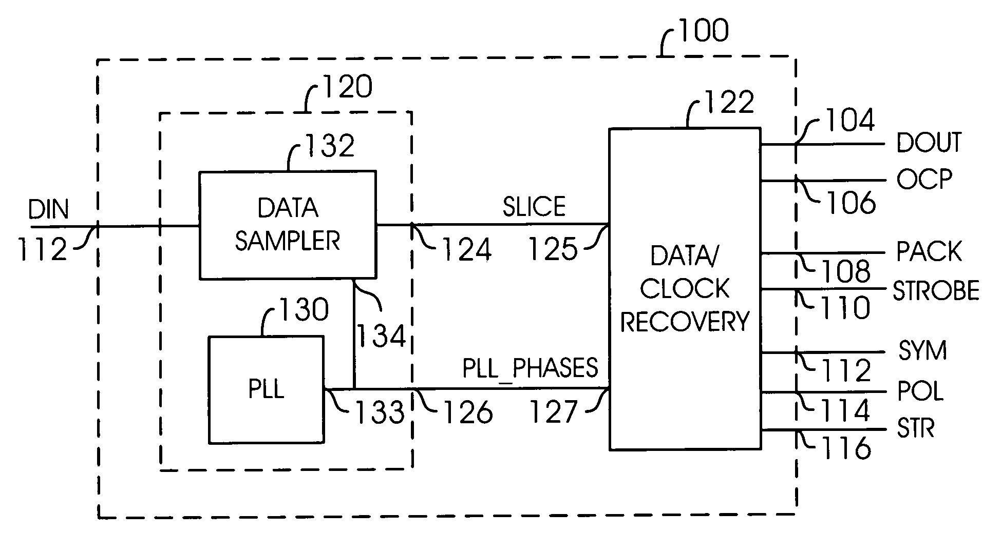
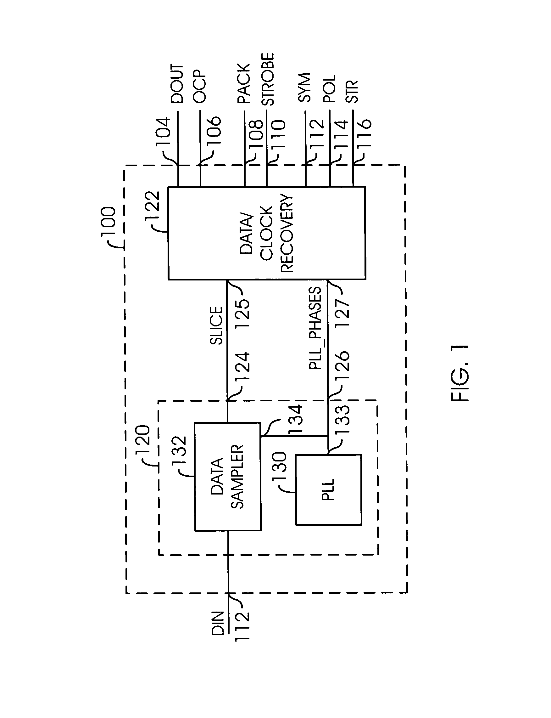
[0026]Referring to FIG. 1, a block diagram of a circuit 100 is shown in accordance with a preferred embodiment of the present invention. The circuit 100 may be implemented as a Digital Clock Recovery Phase Locked Loop (DCRPLL) circuit. The DCRPLL 100 may be a replacement for an Analog Clock Recovery Phase Locked Loop circuit (e.g., a very complex analog circuit used to extract clock and data information from a read channel data stream). The present invention may use digital logic to achieve the same functionality as provided by analog circuits. Therefore, the present invention may be implemented with modern technology, which expects reproducible, dependable performance when many different functions are integrated onto a single silicon integrated circuit.

[0027]The circuit 100 may have an input 102 that may receive a signal (e.g., DIN) and one or more of (i) a set of outputs 104 and 106 that may present serial data signals (e.g., DOUT and OCP), (ii) a set of outputs 108 and 110 that m...


PUM


Abstract

An apparatus comprising an analog circuit and a digital circuit. The analog circuit may be configured to generate a plurality of samples of an input signal in response to a plurality of phases of a reference clock. The digital circuit may be configured to generate an output signal and a clock signal in response to the plurality of samples and the plurality of phases. The clock signal is generally aligned with the output signal.

Description

[0001]This application claims the benefit of U.S. Provisional Application No. 60 / 218,574, filed Jul. 17, 2000, and is hereby incorporated by reference in its entirety.CROSS-REFERENCE TO RELATED APPLICATIONS[0002]The present invention may relate to co-pending applications U.S. Ser. No. 09 / 822,112 and U.S. Ser. No. 09 / 821,886, filed Mar. 30, 2001, which are each hereby incorporated by reference in their entirety.FIELD OF THE INVENTION[0003]The present invention relates to a method and / or architecture for clock and data recovery using a phase locked loop (PLL) generally and, more particularly, to a digital clock recovery phase locked loop (DCRPLL).BACKGROUND OF THE INVENTION[0004]Conventional clock and data recovery systems use a phase locked loop circuit to extract a clock and / or data signal from a serial data stream. The serial data stream may be derived from a number of sources. One such source is a recordable medium, such as a compact disc (CD) or digital video disk (DVD). However,...

Claims


Application Information

Patent Timeline
Patent Type & Authority Patents(United States)
IPC IPC(8): H04L7/00
CPCH04L7/0338H03L7/06
Inventor REUVENI, DAVID R.
Owner AVAGO TECH WIRELESS IP SINGAPORE PTE
Why Eureka
Try Eureka