
Pill dispensing system

a technology of a dispenser and a computer control system, which is applied in the direction of electric programme control, program control, instruments, etc., can solve the problem of only justifiable, typical high-priced devices

Inactive Publication Date: 2006-03-21
PARATA SYST
View PDF35 Cites 95 Cited by
  • Summary
  • Abstract
  • Description
  • Claims
  • Application Information

AI Technical Summary

Benefits of technology

[0047]An alternate embodiment of the apparatus of the present invention provides an alternate bottle dispensing construction. The alternate construction of the bottle dispenser includes a frame having a supporting base with a pair of side walls with a space therebetween and a bottle dispensing opening at the bottom of the frame. A plurality of inclined plates are positioned in between the side walls and supported by the frame, each of the plates being sized to carry a plurality of bottles to be dispensed. The inclined orientation of the plates enables the bottles to move toward the front of the frame under the influence of gravity.

Problems solved by technology

These are typically very expensive devices that are only justifiable to very large end users such as hospitals.

Method used


Image

  • Pill dispensing system
  • Pill dispensing system
  • Pill dispensing system

Examples


Embodiment Construction

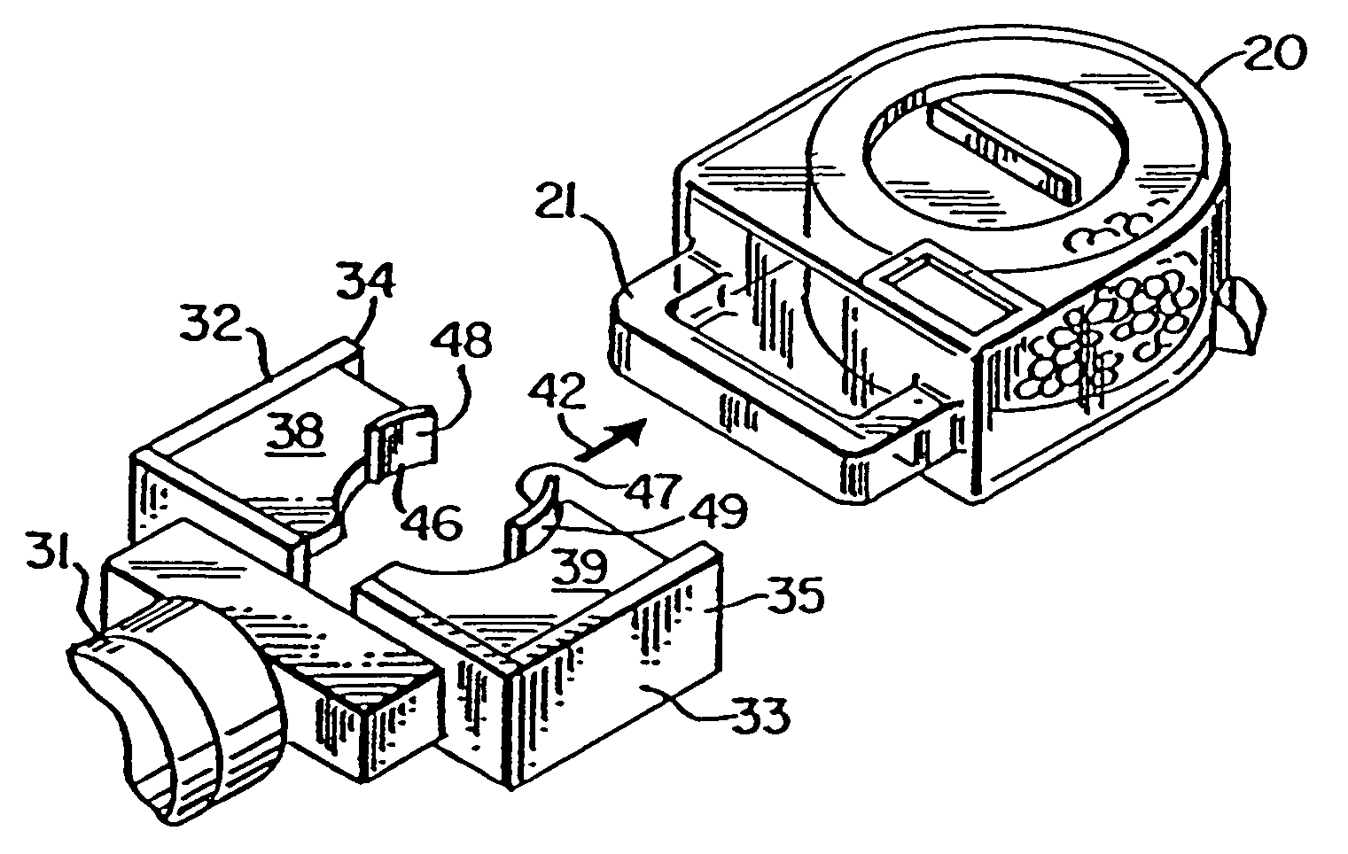
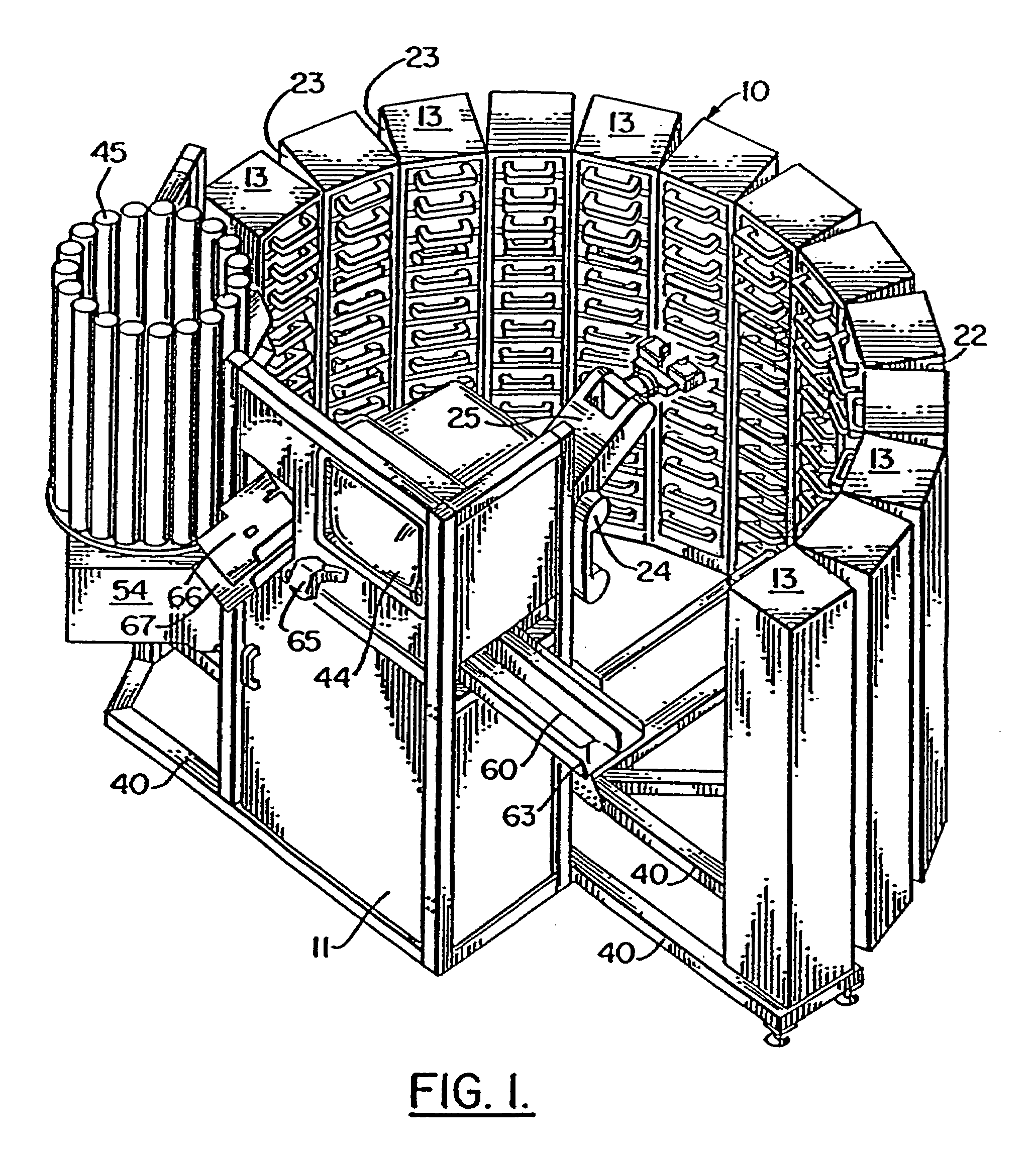
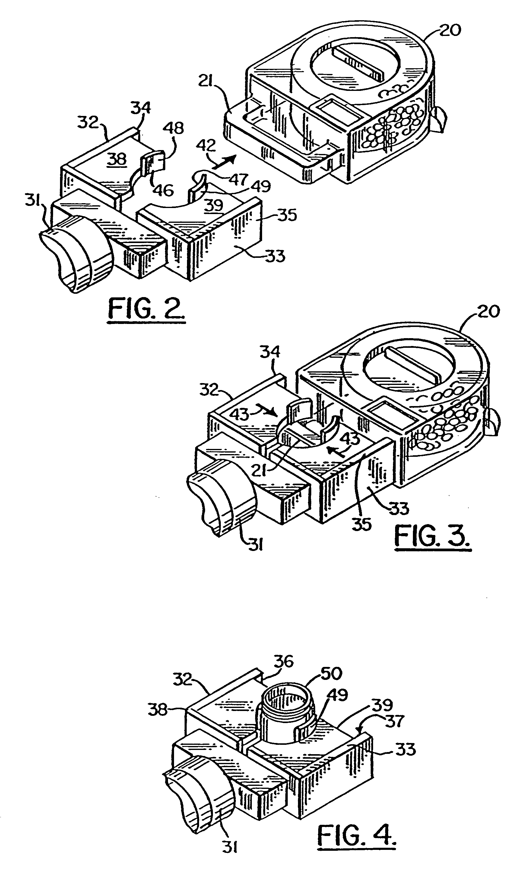
[0074]FIGS. 1–6 show the preferred embodiment of the apparatus of the present invention, designated generally by the numeral 10 in FIG. 1. In FIGS. 1 and 6, pill dispensing apparatus 10 includes generally the various components supported on frame 40, an operator's console 11, a shelving unit 12, robot 24, and a frame 40. Frame 40 supports shelving unit 12, console 11, robot 24, a label printing and applying device 54, and a counter / dispenser 60, and pill bottle dispenser 45.

[0075]Frame 40 can be provided with a plurality of feet 41 for engaging an underlying surface, shop floor, concrete slab, or the like.

[0076]Shelving unit 12 is seen in FIGS. 1 and 5. The shelving unit 12 includes a plurality of vertically extending column members 13 each having a top panel 14, a bottom panel 15, a rear panel 16, and side walls 22, 23.

[0077]A generally flat front surface 17 is provided to each column 13 as defined by the front edge of side walls 22, 23 and the front edge of shelves 18. The shelves...


PUM


Abstract

A pill dispensing system includes a shelving unit in array form that holds a number of bulk containers, each holding a bulk amount of a pill to be dispensed. A computer controlled robot removes a selected bulk container and places it on a counter that also dispenses pills. The robot has an arm with a free end portion that can grip a bulk container or a single pill bottle to be filled. The robot is computer controlled to retrieve an empty pill bottle, place it on a label printing and applying unit, then place it next to the counter / dispenser to receive the selected number of selected prescription pills, then place the filled, labeled bottle on a conveyor. In an alternate embodiment, pill bottles are dispensed from a dispenser that holds bottles on inclined plates and feeds them to a vertical dispensing channel. Gates prevent the flow of bottles from an inclined position until the plate above has been emptied.

Description

CROSS-REFERENCE TO RELATED APPLICATIONS[0001]This application is a continuation of U.S. patent application Ser. No. 10 / 655,226 filed Sep. 4, 2003, now U.S. Pat. No. 6,775,589, which is a continuation of U.S. patent application Ser. No. 10 / 233,807 filed Sep. 3, 2002, now U.S. Pat. No. 6,681,149, which is a continuation of U.S. patent application Ser. No. 09 / 768,200, filed Jan. 23, 2001 now abandoned, which is a continuation of U.S. patent application Ser. No. 09 / 205,246, filed Dec. 4, 1998, now U.S. Pat. No. 6,176,392, which is a continuation-in-part of U.S. patent application Ser. No. 08 / 986,665, filed Dec. 8, 1997, now U.S. Pat. No. 6,036,812, which is a continuation-in-part of U.S. patent application Ser. No. 08 / 986,247, filed Dec. 5, 1997, now U.S. Pat. No. 6,006,946, which are incorporated herein by reference.STATEMENT REGARDING FEDERALLY SPONSORED RESEARCH OR DEVELOPMENT[0002]Not applicableREFERENCE TO A “MICROFICHE APPENDIX”[0003]Not applicableBACKGROUND OF THE INVENTION[0004]...

Claims


Application Information

Patent Timeline
IPC IPC(8): G06F7/00G05B19/04G05B19/18G06F17/00B65B43/44A61J7/00B65G1/04G07F11/62
CPCG07F11/165G07F11/24G07F17/0092G07F11/44G07F11/62G07F11/32B65B5/103B65G1/045G16H20/13
Inventor WILLIAM, JEFFREY P.POTEPALOV, GALINADOLORES, ALLANBERGERON, MICHAEL
Owner PARATA SYST
Features
  • Generate Ideas
  • Intellectual Property
  • Life Sciences
  • Materials
  • Tech Scout
  • Unparalleled Data Quality
  • Higher Quality Content
  • 60% Fewer Hallucinations
Learn More