Deterrent strip for repelling birds and other pests

a technology of repellent strips and strips, which is applied in the field of strips, can solve the problems of difficult roll up of strips and form compact rolls

Inactive Publication Date: 2006-04-04
SNOW ROGER
View PDF22 Cites 23 Cited by
  • Summary
  • Abstract
  • Description
  • Claims
  • Application Information

AI Technical Summary

Problems solved by technology

While the device disclosed in my above-referenced application is highly effective for its intended purpose, it has been found that the placement of the restraint members in the strip center at the strip bottom makes it difficult to roll up the strip and form a compact roll suitable for example for storage and transport.

Method used


Image

  • Deterrent strip for repelling birds and other pests
  • Deterrent strip for repelling birds and other pests
  • Deterrent strip for repelling birds and other pests

Examples


Embodiment Construction

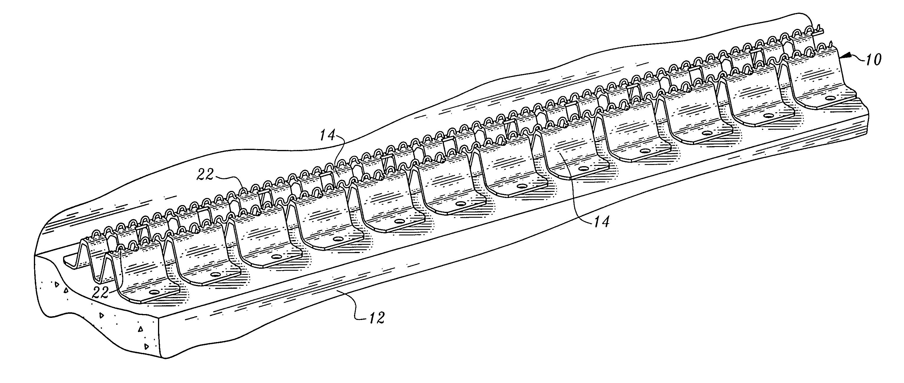
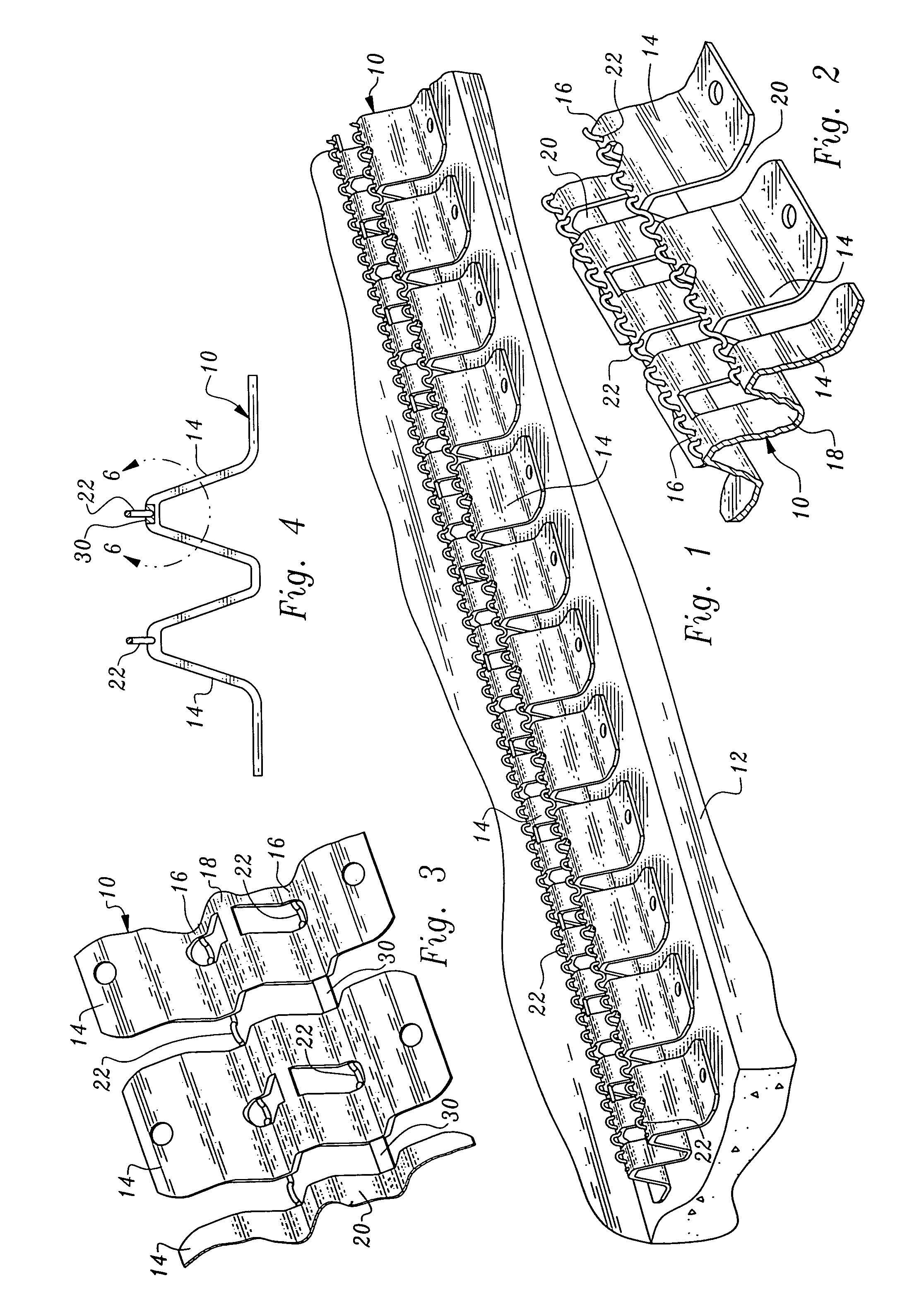
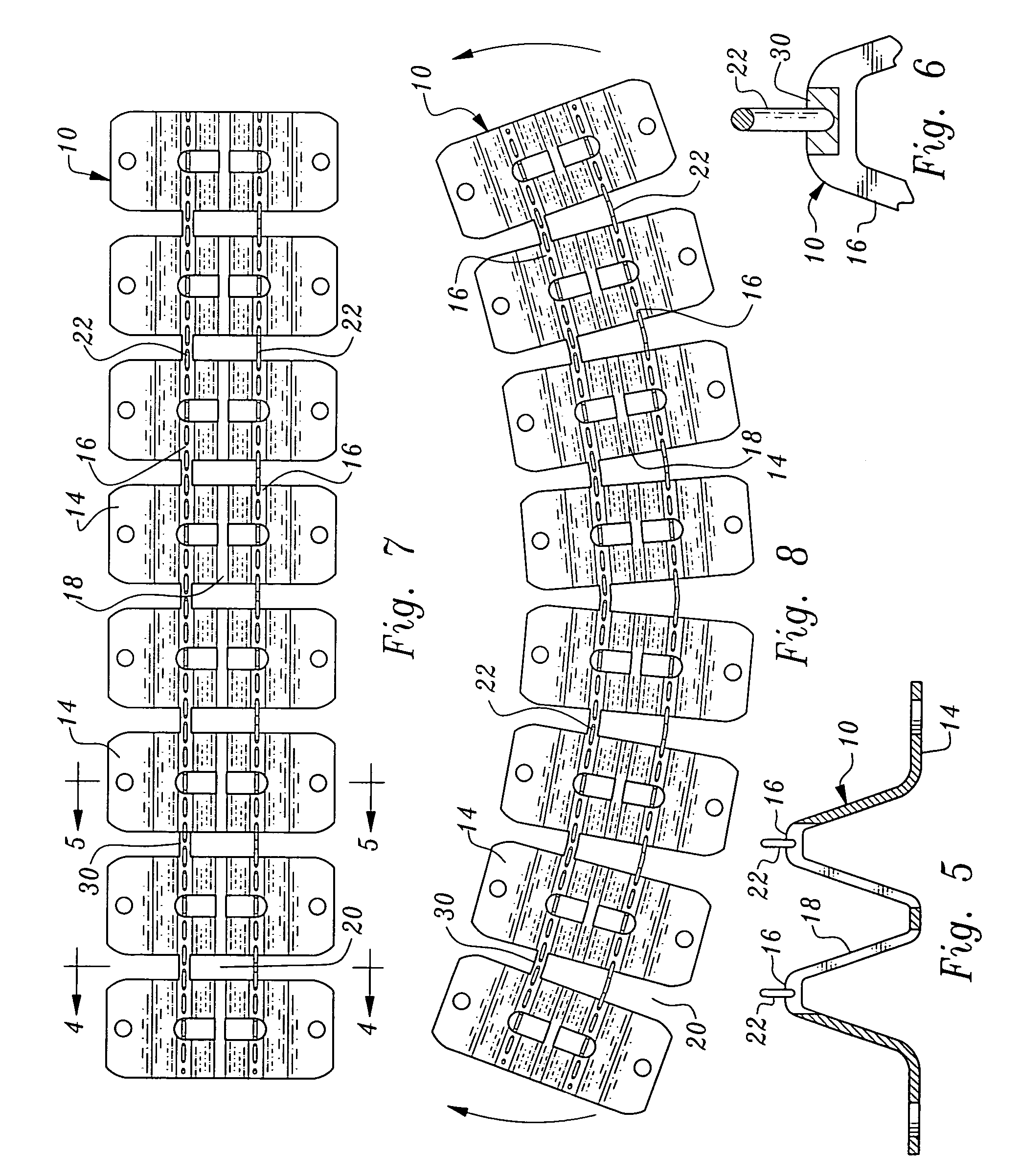
[0024]Referring now to FIGS. 1–8, a strip 10 constructed in accordance with the teachings of the present invention is illustrated. The strip 10 is a deterrent strip for repelling birds and other pests. In FIG. 1, a length of the strip 10 is shown mounted on the ledge 12 of a building, a typical but not exclusive setting for use of the strip.

[0025]The strip includes a flexible, bendable base which is comprised of a plurality of wire support members 14 of electrically non-conductive material, for example plastic. Each wire support member includes two spaced wire support portions 16 and an inner portion 18. The wire support portions are elevated relative to the inner portion. Adjacent wire support members define spaces 20 therebetween extending the full width of the strip. The spaces provide flexibility to the base whereby it may be bent both out of plane and within plane.

[0026]Strip 10 also includes two electrically conductive wires 22 which are crimped so that they are somewhat exten...


PUM


Abstract

A deterrent strip for repelling birds and other pests includes two electrical wire support members separated by spaces extending across the strip to allow bending. Connectors are attached to the wire support members to resist lengthwise stretching of the strip, the connectors extending across the spaces and offset from the center of the strip.

Description

[0001]This application is a continuation-in-part of my U.S. patent application Ser. No. 10 / 781,952, filed Feb. 19, 2004 now U.S. Pat. No. 6,928,768.TECHNICAL FIELD[0002]This invention relates to a pest repelling device, and more particularly to a strip which may be secured to buildings, statues or other objects to discourage birds and other pests from resting thereon.BACKGROUND OF THE INVENTION[0003]U.S. Pat. No. 6,383,064, issued Sep. 4, 2001, discloses a pest repelling device co-invented by the inventor of the present invention.[0004]The device of U.S. Pat. No. 6,383,064 relates to an elongated deterrent strip for mounting to an inanimate object to discourage birds and other pests from resting on that object. The strip includes a base of electrically non-conductive material. The strip in lateral cross-section has peripheral edges normally lying in a plane and a raised concave center portion. The base has spaced notches along each edge to provide flexibility to the base, whereby th...

Claims


Application Information

Patent Timeline
Patent Type & Authority Patents(United States)
IPC IPC(8): A01K3/00A01M29/26
CPCA01M29/26
Inventor SNOW, ROGER
Owner SNOW ROGER
Why Eureka
Try Eureka