Power supply for measuring the line impedance of underground cable

a technology of power supply and underground cable, which is applied in the direction of electric variable regulation, process and machine control, instruments, etc., can solve the problems of large errors in measured impedance values, difficulty in boosting power, and cut in power of underground cable lines or breakage of impedance measurement equipment, etc., to achieve the effect of removing nois

a technology of power supply and underground cable, which is applied in the direction of electric variable regulation, process and machine control, instruments, etc., can solve the problems of large errors in measured impedance values, difficulty in boosting power, and cut in power of underground cable lines or breakage of impedance measurement equipment, etc., to achieve the effect of removing nois

US7023675B2Inactive Publication Date: 2006-04-04LG CABLE LTD (KR)

Image

  • Power supply for measuring the line impedance of underground cable
  • Power supply for measuring the line impedance of underground cable
  • Power supply for measuring the line impedance of underground cable

Examples


Embodiment Construction

[0011]Now, a preferred embodiment of the present invention will be described in detail with reference to the drawings.

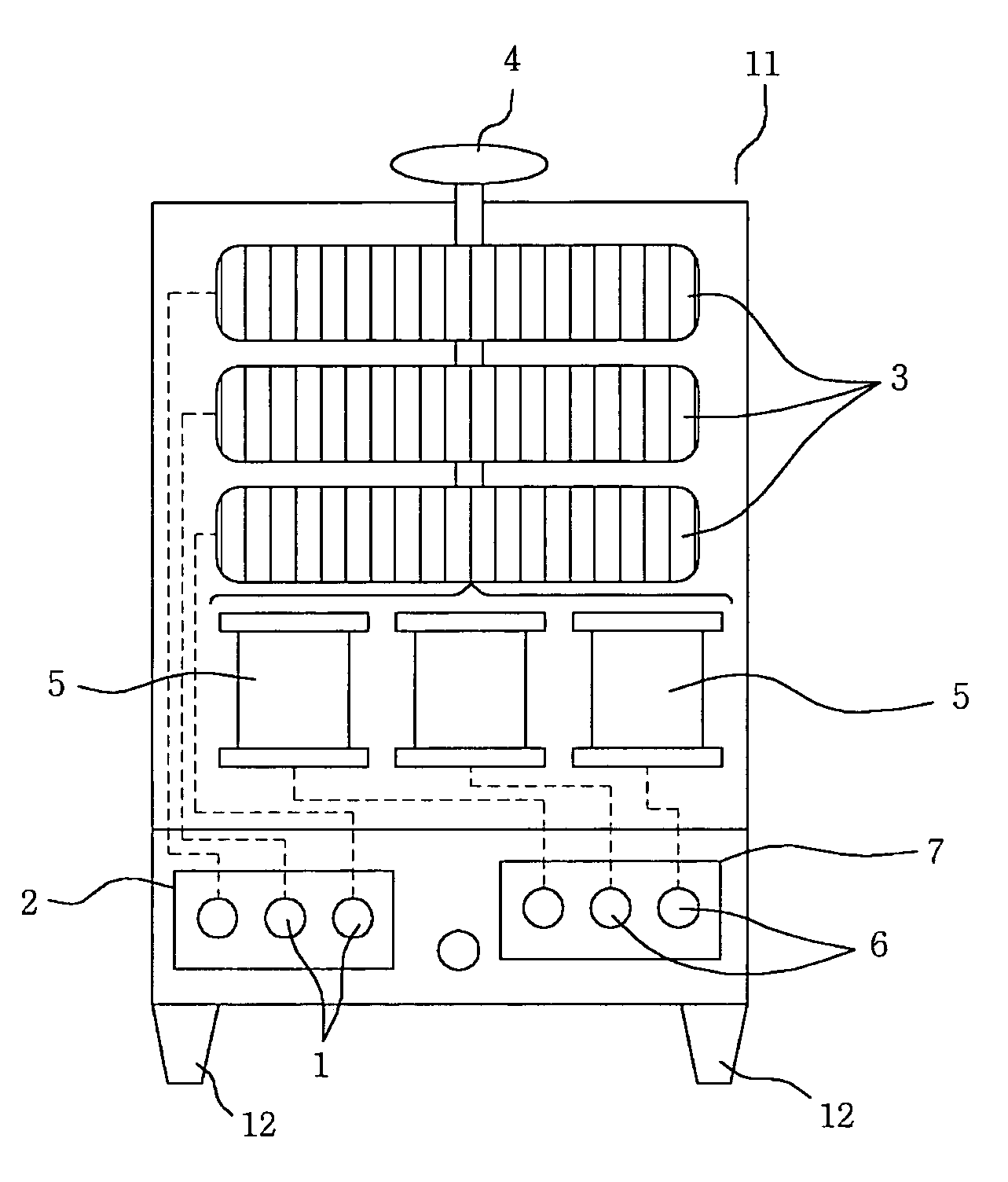
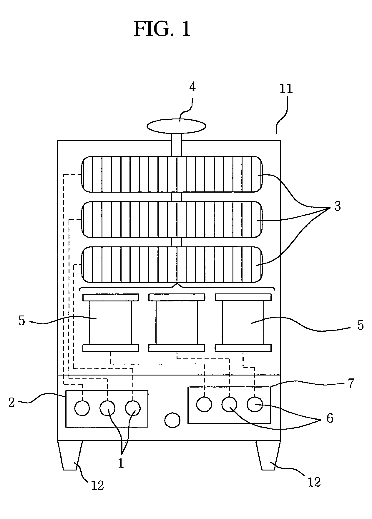
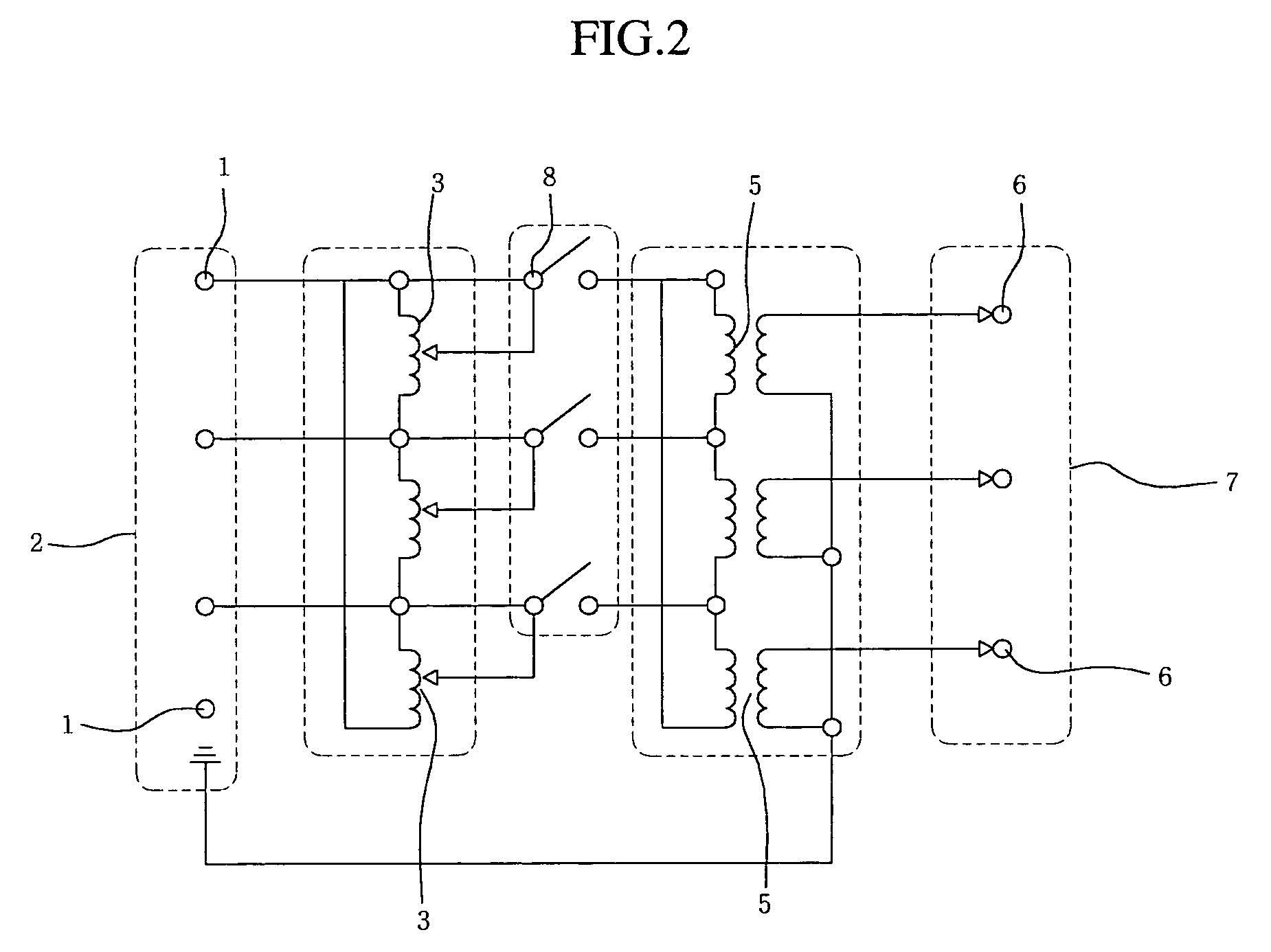
[0012]As shown in FIGS. 1 and 2, in order to measure the impedance of a three-phase underground cable, an input terminal section 2 composed of three input terminals 1 is formed on a body 11 of a specific size at a lower portion thereof. Each input terminal 1 of the input terminal section 2 is individually connected to the utility power, so that powers to be used to measure the underground cable impedance are inputted to the input terminals 1, respectively.

[0013]Three autotransformers 3 connected respectively to the input terminals 1 of the input terminal section 2 are formed vertically in parallel inside the body 11 at an upper portion. A transformer adjustment tap 4, connected to all three of the autotransformers 3, is formed on the body 11 at an upper portion thereof. The transformer adjustment tap 4 simultaneously controls the autotransformers 3 to equally transfo...


PUM

PropertyMeasurementUnit
impedanceaaaaaaaaaa
voltageaaaaaaaaaa
currentaaaaaaaaaa

Abstract

Disclosed is a power supply for measuring the line impedance of an underground cable, which includes an input terminal section having a plurality of input terminals, a plurality of autotransformers, a transformer adjustment tap, a plurality of 3rd-harmonics cancellation transformers, and an output terminal section having a plurality of output terminals. The autotransformers are connected respectively to the input terminals. The transformer adjustment tap is connected to all of the autotransformers. The 3rd-harmonics cancellation transformers are connected respectively to the autotransformers. The output terminals are connected respectively to the 3rd-harmonics cancellation transformers. The autotransformers are simultaneously controlled by the transformer adjustment tap so as to uniformly boost the powers supplied respectively to the autotransformers, and 3rd-harmonics of the powers are cancelled in the 3rd-harmonics cancellation transformers to remove noise, so that the powers are stably applied respectively to the phases of the underground cable.

Description

BACKGROUND OF THE INVENTION[0001]1. Field of the Invention[0002]The present invention relates to a power supply for measuring the line impedance of an underground cable, and more particularly to a power supply for measuring the line impedance of an underground cable comprising an input terminal section including a plurality of input terminals connected to a power source; a plurality of autotransformers connected respectively to the input terminals of the input terminal section; a transformer adjustment tap connected to all of the autotransformers; a plurality of 3rd-harmonics cancellation transformers connected respectively to the autotransformers; and an output terminal section including a plurality of output terminals connected respectively to the 3rd-harmonics cancellation transformers, whereby the autotransformers are simultaneously controlled by the transformer adjustment tap to equally transform power supply voltages supplied respectively to the autotransformers, and 3rd-harmo...

Claims


Application Information

Patent Timeline
04 Apr 2006
Publication
US7023675B2
IPC
H02H9/08; G01R27/26; G01R27/16; G05F1/14; H01F27/34; H01F27/38; H01F29/02; H01F30/02
CPC
G01R27/04; G01R27/16; H01F30/02; H01F27/385; H01F29/02; H01F27/34; G01R27/26
Inventors
HA, CHE-WUNG; KIM, JUNG-NYUN