Device for the application of a hair product to sections of hair

a hair product and hair technology, applied in the field of hair product application devices, can solve the problems of affecting the natural appearance of the hair, and the tedious technique of dyeing caps, so as to avoid or minimize the drawbacks

Inactive Publication Date: 2006-04-11
LOREAL SA
View PDF22 Cites 66 Cited by
  • Summary
  • Abstract
  • Description
  • Claims
  • Application Information

AI Technical Summary

Benefits of technology

[0011]It is an object of the invention to provide a device for applying a hair product to sections of hair while avoiding or minimizing the drawbacks discussed above.

Problems solved by technology

The dyeing cap technique is very tedious and has at least three major drawbacks.
Specifically, after the cap is put on, the hair is flattened and the sections of hair are randomly extracted through the holes which can lead to a result, particularly in terms of the distribution of the sections of hair, which is quite different from the intended result.
As this diameter is usually small (typically about 1 mm to 2 mm), there is poor juxtaposition of the sections of hair.
In addition, due to the thickness of the cap and the thickness of the sections of hair, and because the extracted hair is not necessarily the hair whose connection to the scalp is directly beneath the hole through which it is extracted, the dye product deposited by this technique clearly does not go to the roots of the hair, thereby detracting from the natural appearance of the result.
Such devices generally suffer from the same drawbacks as described above relating particularly to the fact that they are used by approaching the hair from the exterior or top of the hair.
The result obtained is therefore far from satisfactory.
Moreover, with such a configuration there is a danger that the product will drip out of the reservoir during application.

Method used


Image

  • Device for the application of a hair product to sections of hair
  • Device for the application of a hair product to sections of hair
  • Device for the application of a hair product to sections of hair

Examples


first embodiment

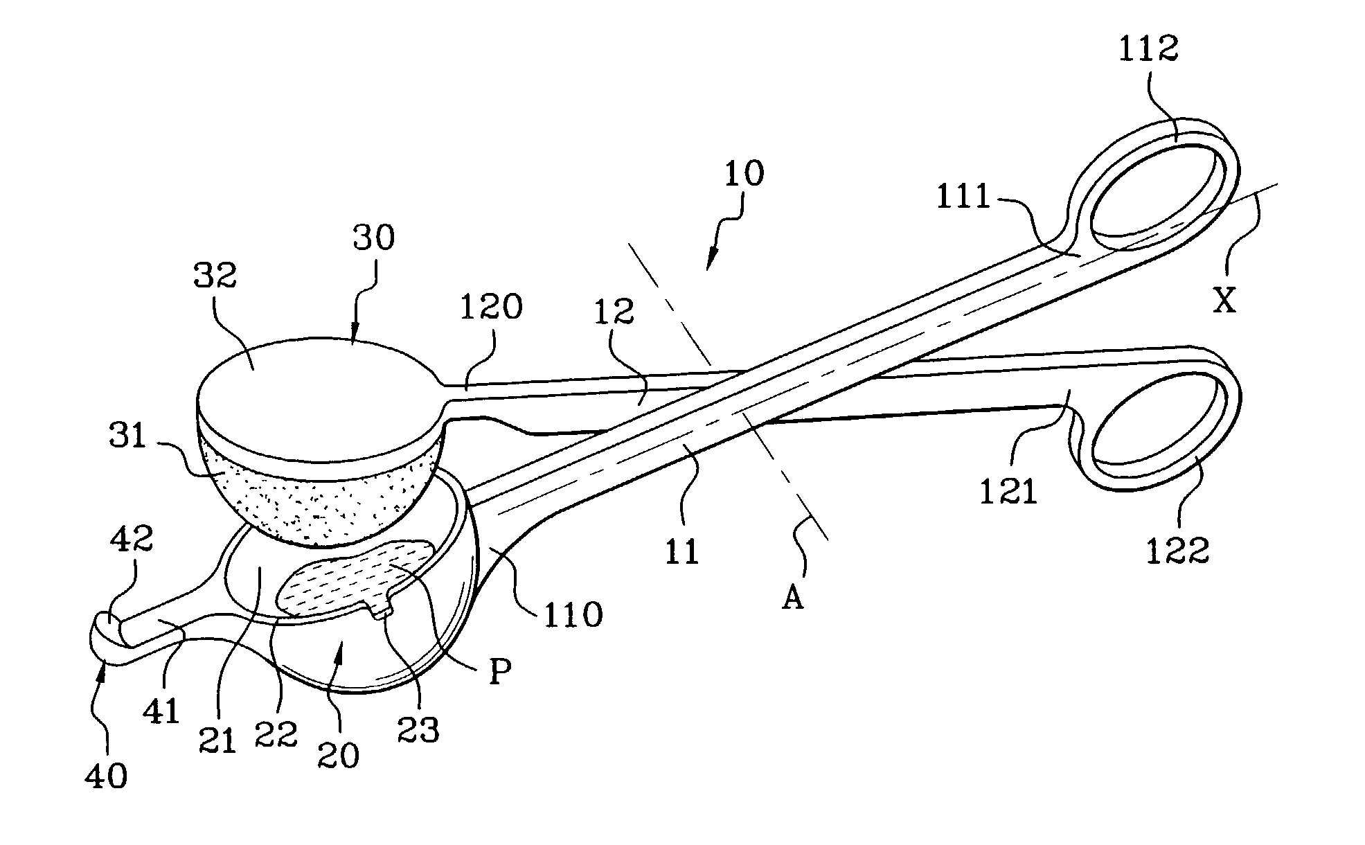
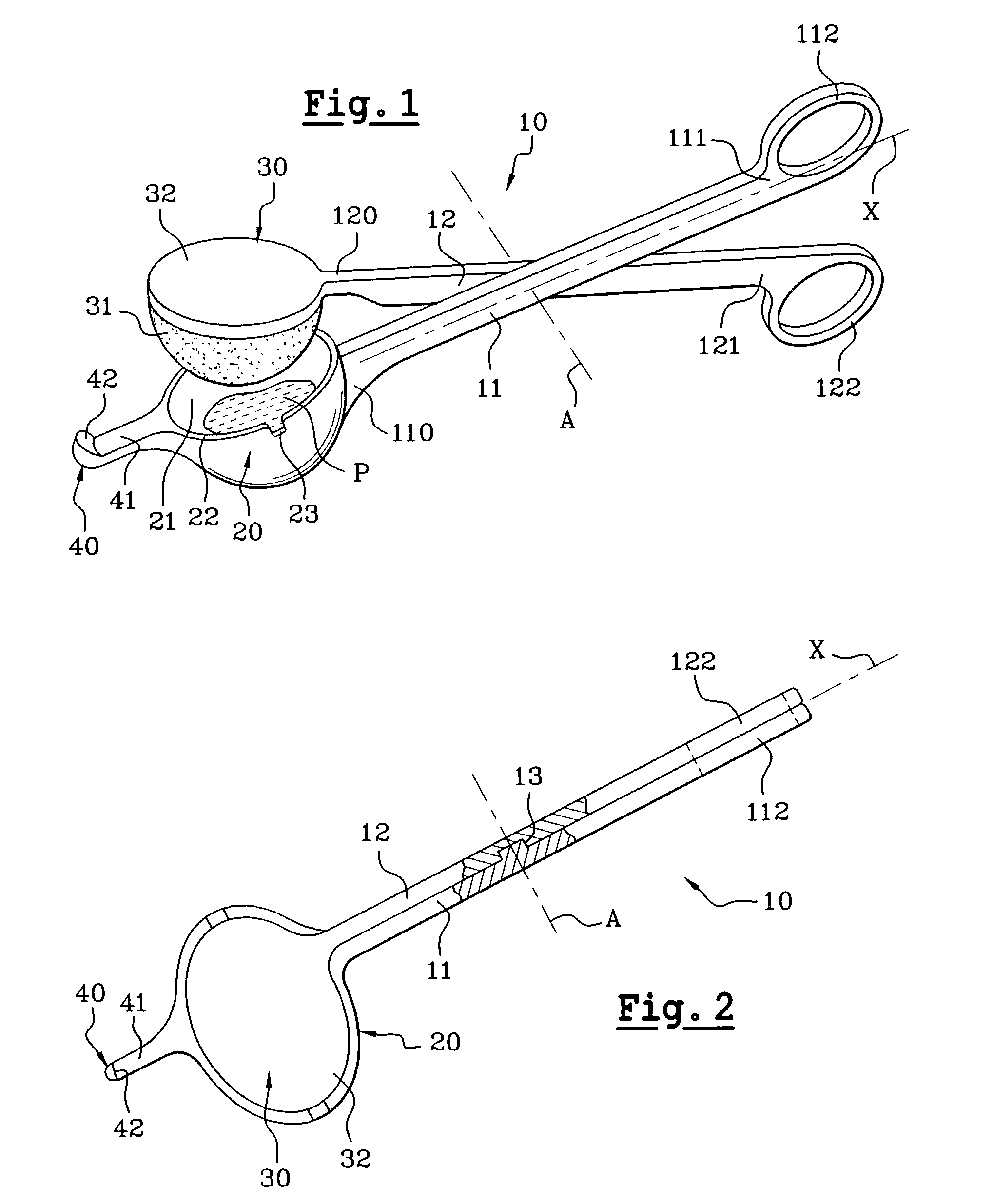
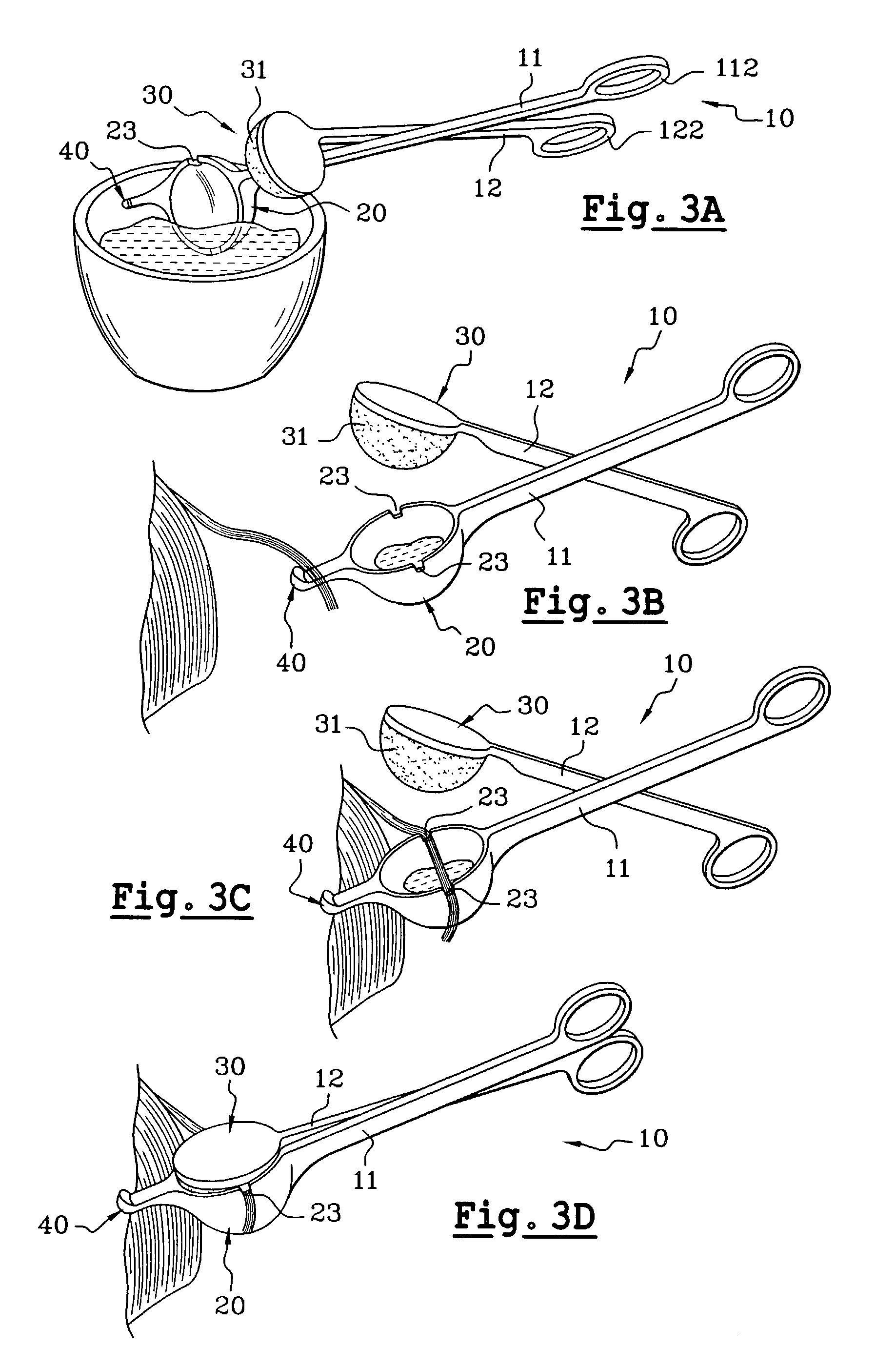
[0037]FIGS. 1 to 3 depict the device 10 for the application of a hair product to sections of hair of a hair product. The device 10 includes two arms 11 and 12 hinged to each other so as to be able to pivot about an axis A. In the preferred form illustrated, the two arms are of approximately the same length. By way of example, the arms can be snap-fitted together utilizing a projection 13 on one of the arms which fits into an orifice on the other arm so as to provide a pivot coupling about the axis A similar to that utilized in a pair of scissors. As an alternative, the two arms may be riveted together or coupled by other fastening expedients to provide a hinge or pivot coupling. Each arm is preferably formed as a single molded piece, and the arms are then fitted together. It is to be understood, however, that it is also possible to form the arms of multiple pieces. The two arms are preferably made from a thermoplastic material such as a polyolefin. According to one of the advantageo...

second embodiment

[0050]The second embodiment shown in FIG. 4 is identical to that described in conformity with FIGS. 1 to 3 as far as the cavity 20 and retention member 30 are concerned. In this embodiment, the arms 11 and 12 have no rings at their ends 111 and 121. Each arm 11 and 12 has two angled portions 11a, 11b and 12a, 12b, respectively, situated on either side of the axis of rotation A. The portions 11b and 12b have respective ends 111 and 121 which act as the handles. When the portions 11a and 12a are approximately aligned, the portions 11b and 12b are separated. The portions 11b and 12b are connected to each other by a spring 14 in the manner of a pair of secateurs. The spring 14 works in compression and is mounted on the arms in such a way that when it is at rest, that is when not compressed by the user, the block of foam 31 is held inside the cavity 20. To remove the block of foam from the cavity, the user squeezes the two ends 111 and 121 of the two portions of the arms 11b and 12b toge...

third embodiment

[0051]The third embodiment shown in FIG. 5 is identical to that described in conformity with FIGS. 1 to 3 as far as the cavity 20 and retention member 30 are concerned, but this time it is made in one piece 100 so as to form U-shaped tongs. One of the free ends 101 of the arms of the U is provided with the cavity 20 and the other of the free ends 102 of the arms of the U is provided with the retention member 30. The two arms of the U pivot about an axis B situated, with this arrangement, at the base 103 of the U. In this embodiment, essentially the entire device can be formed as a single molding (except, e.g., the impregnatable or absorbable material associated with the retention member and / or the cavity).


PUM


Abstract

A device for applying a hair product to sections of hair includes a first part having an open cavity to contain the hair product. The product is applied to the section of hair by contacting the section of hair with the product inside the cavity and moving the device relative to the section of hair. The device also includes a second part having a retention member that is movable relative to the cavity to selectively open and close the cavity. When closed, the retention member keeps the section of hair in contact with the product inside the cavity as the device moves relative to the section of hair. The retention member preferably includes a porous and/or fibrous element that can absorb or in other words be impregnated with the hair product.

Description

CROSS REFERENCE TO RELATED APPLICATIONS[0001]This document claims priority to French application number 0109234 filed Jul. 11, 2001, the entire content of which is hereby incorporated by reference.BACKGROUND OF THE INVENTION[0002]1. Field of the Invention[0003]The present invention relates to a device for the application of a hair product to sections of hair. The invention is particularly suitable for the application of a dye product to sections of hair.[0004]2. Discussion of Background[0005]There are a number of types of hair dye products: temporary dyes, semi-permanent dyes, and permanent or oxidation dyes. These dye products can be provided in the form of a cream, a foam, or a liquid of greater or lesser viscosity. Dye products in liquid or gel form can be used after mixing, if necessary, from a pan or from a bowl.[0006]Dyes used from a bowl can be applied to the entire head of hair, with all of the hair impregnated with the product, and with the aim being to modify the color of ...

Claims


Application Information

Patent Timeline
Patent Type & Authority Patents(United States)
IPC IPC(8): A45D19/18A46B11/00A46B15/00A45D19/00A45D19/02
CPCA45D19/02A45D2019/0091A45D19/0066A45D19/028A45D19/024
Inventor THIEBAUT, LAURE
Owner LOREAL SA
Why Eureka
Try Eureka