Electronic door latch system with water rejection filtering

a technology of electronic control system and door latch, which is applied in the direction of electrical locking circuit, anti-theft device, pulse technique, etc., can solve the problems of conventional field effect sensor not ideally suited for harsh environments, failure of switch, and inoperable membrane switch

Active Publication Date: 2006-04-11
TOUCHSENSOR TECH
View PDF16 Cites 53 Cited by
  • Summary
  • Abstract
  • Description
  • Claims
  • Application Information

AI Technical Summary

Problems solved by technology

As such, the protective cover can deteriorate and crack, allowing moisture and contaminants to enter the internals of the switch, ultimately leading to failure of the switch.
Further, ice buildup, as is common in northern climates in the winter months, can render a membrane switch inoperable.
However, conventional field effect sensors are not ideally suited for harsh environments, such as the outside of an automobile, because they also can be unintentionally actuated by other stimuli, such as pooled or flowing water or other contaminants.
As such, an electrically operated automobile door latch controlled by a conventional field effect sensor could release spuriously and unintentionally when the automobile is parked in the rain or run through a carwash.

Method used


Image

  • Electronic door latch system with water rejection filtering
  • Electronic door latch system with water rejection filtering
  • Electronic door latch system with water rejection filtering

Examples


Embodiment Construction

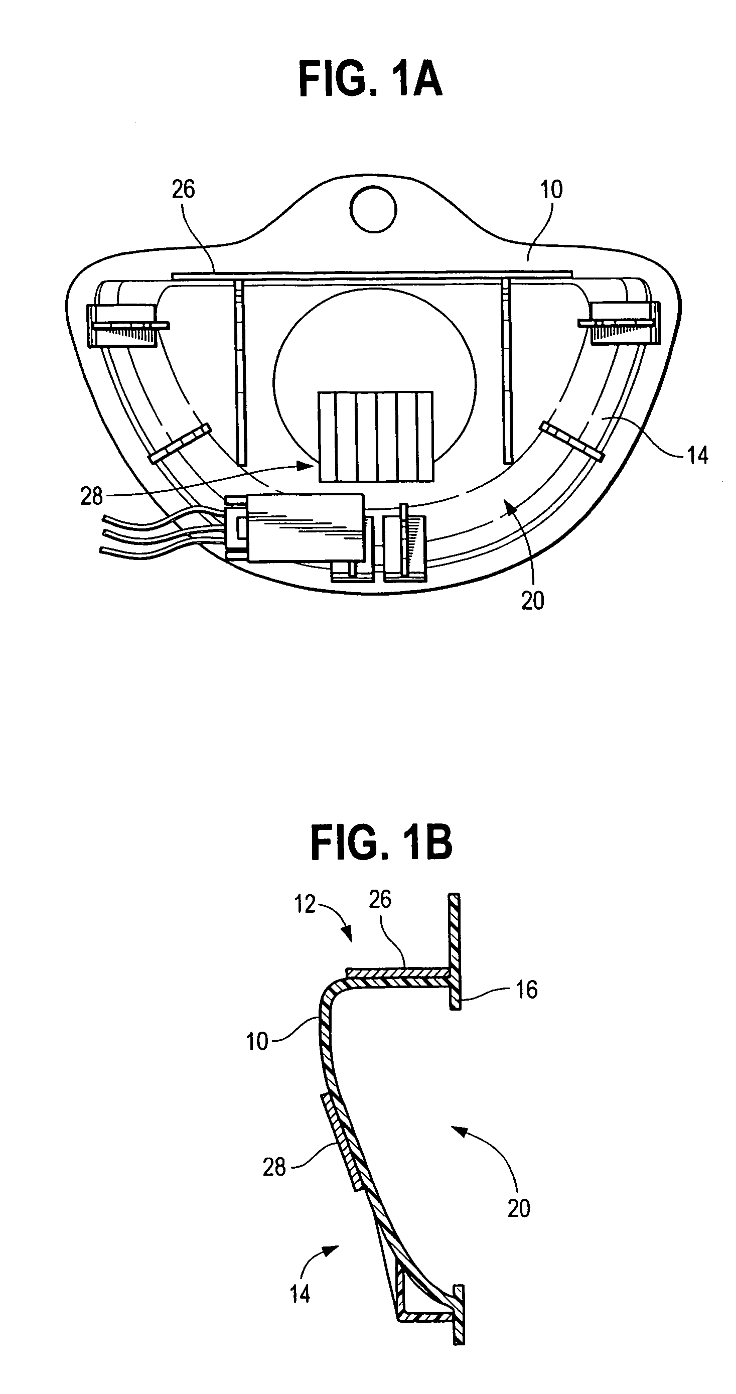
[0014]FIGS. 1A and 1B illustrate a handle shell 10 as be would installed in a lift-gate or door of an automobile. Shell 10 includes a substantially flat portion 12, a substantially curved portion 14 and a lip 16, wherein flat portion 12 defines an upper surface 18 and a lower surface 20, curved portion 14 defines a concavity 20 having an outer surface 20 and an inner surface 22, and lip 16 defines a rear surface 24. Shell 10 typically would be installed with flat portion 12 oriented toward the top of the lift gate or door and curved portion 14 oriented toward the bottom of the lift gate or door. Shell 10 typically would be configured to receive a person's hand, with palm facing away from shell 10, such that the person's fingertips would extend to lower surface 20 of flat portion 12 and rear surface 24 of lip 16.

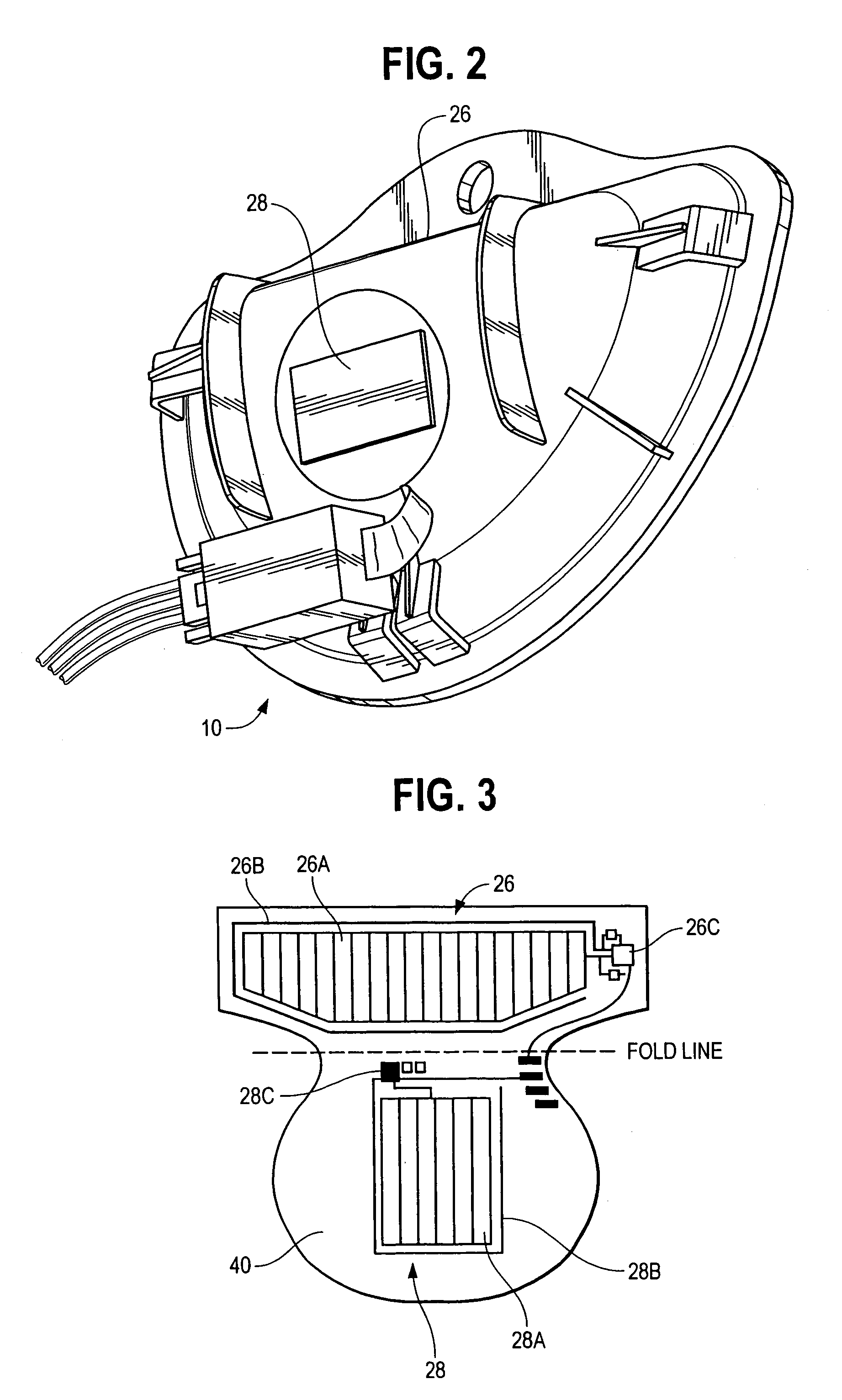
[0015]Referring to FIG. 2, a first field effect sensor, or touch sensor, 26 is positioned on upper surface 18 of flat portion 12. As discussed below and illustrated in FIGS. ...


PUM

PropertyMeasurementUnit
timeaaaaaaaaaa
timeaaaaaaaaaa
electricaaaaaaaaaa

Abstract

A control circuit receives inputs from first and second field effect sensors. The control circuit produces a control output only if the second field effect sensor senses proximity or touch more than a predetermined time after the first field effect sensor senses proximity or touch.

Description

CROSS REFERENCE TO RELATED APPLICATIONS[0001]This application claims priority from U.S. Provisional Patent Application Ser. No. 60 / 464,518, entitled “Electronic Door Latch System with Water Rejection Filtering” and filed on Apr. 22, 2003, the disclosure of which is incorporated herein by reference.BACKGROUND OF THE INVENTION[0002]1. The Technical Field[0003]The present invention is directed to an electronic control system for a door latch release mechanism, including means for rejecting false actuation signals caused by environmental effects or otherwise.[0004]2. The Related Art[0005]Common automobile door latches are purely mechanical devices having a mechanical latch and a mechanical release mechanism operated by a mechanical pushbutton, pull handle, or the like. In recent years, some automobile manufacturers have offered electrically-operated door latch mechanisms. These mechanisms typically use a conventional mechanical latch with an electrically-operated release mechanism contr...

Claims


Application Information

Patent Timeline
Patent Type & Authority Patents(United States)
IPC IPC(8): H03K17/945B60R25/01B60R25/20B60R25/30E05B17/00E05B65/20H03K17/94H03K17/96
CPCE05B81/76H03K17/96E05B81/77E05B77/34H03K17/94E05B81/54
Inventor STEENWYK, TIMOTHY EDWARD
Owner TOUCHSENSOR TECH
Why Eureka
Try Eureka