Low-loss coupler

a low-loss coupler and coupler technology, applied in coupling devices, electrical devices, waveguides, etc., can solve the problems of total cancellation at the other input ports, cancellation of most components, and only constructive interference of one signal component, so as to achieve low loss insertion and high port isolation

Inactive Publication Date: 2006-04-11
LUCENT TECH INC +1
View PDF11 Cites 2 Cited by
  • Summary
  • Abstract
  • Description
  • Claims
  • Application Information

AI Technical Summary

Benefits of technology

[0009]One aspect of the present invention is seen in a coupler including a first set of ports coupled to a first ring, a second set of ports coupled to a second ring, and a plurality of connecting elements coupled between the first and second rings. The coupler provides low loss insertion and high port isolation and may be used as a standalone coupler or as an elementary device for building Butler matrices of varying configurations.

Problems solved by technology

This splitting, amplifying, and combining operation takes advantage of coherent superposition on the coupler's output ports, which may lead to the cancellation of most components, and constructive interference for only one of the signal components.
The different paths subject the signal to different phase changes along the different paths, which can result in a total cancellation at the other input ports, or a partial constructive superposition on the output ports.
Accordingly, the design of the network is not readily implemented using a regular 2n Butler matrix.
Commercially available devices for implementing such networks have significant disadvantages.
Moreover, the commercially available devices show a port isolation not better than −20 dB.
These limitations can lead to increased crosstalk between adjacent sectors, thus degrading the system capacity due to an increased interference level.

Method used


Image

  • Low-loss coupler
  • Low-loss coupler
  • Low-loss coupler

Examples


Embodiment Construction

[0017]Illustrative embodiments of the invention are described below. In the interest of clarity, not all features of an actual implementation are described in this specification. It will of course be appreciated that in the development of any such actual embodiment, numerous implementation-specific decisions must be made to achieve the developers' specific goals, such as compliance with system-related and business-related constraints, which will vary from one implementation to another. Moreover, it will be appreciated that such a development effort might be complex and time-consuming, but would nevertheless be a routine undertaking for those of ordinary skill in the art having the benefit of this disclosure.

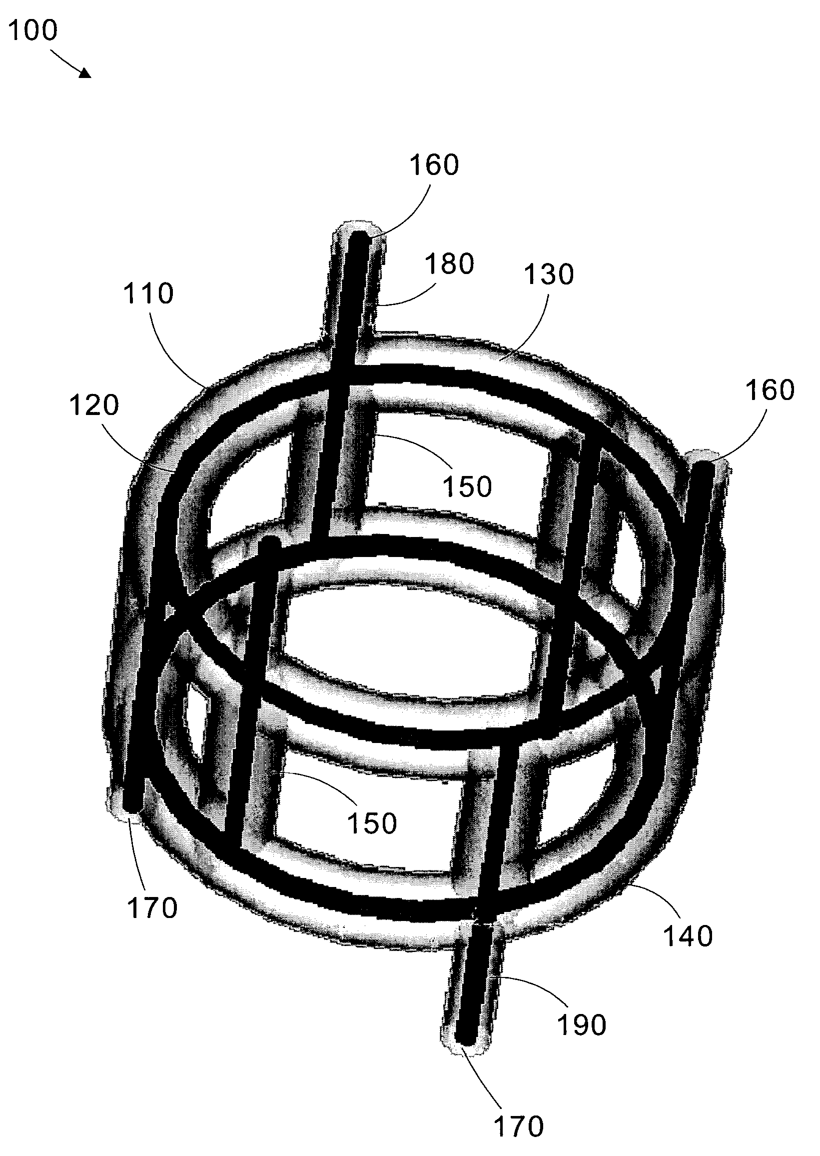
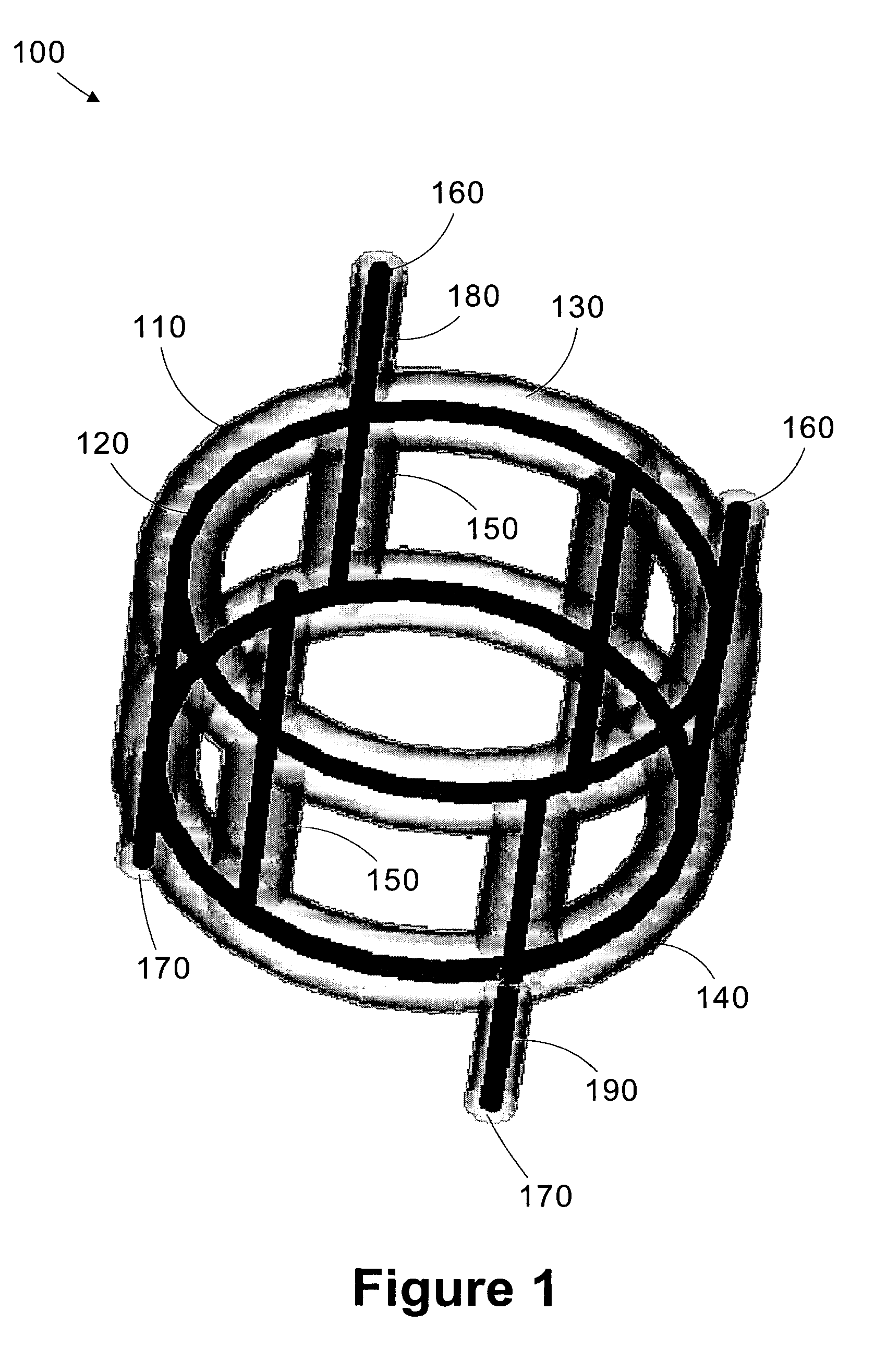
[0018]Turning now to FIG. 1, an isometric diagram of a coupler 100 in accordance with one illustrative embodiment of the present invention is shown. In the embodiment illustrated in FIG. 1, the coupler 100 is implemented using a coaxial transmission line having an outer conductor...


PUM


Abstract

A coupler includes a first set of ports coupled to a first ring, a second set of ports coupled to a second ring, and a plurality of connecting elements coupled between the first and second rings. The coupler provides low loss insertion and high port isolation and may be used as a standalone coupler or as an elementary device for building Butler matrices of varying configurations.

Description

BACKGROUND OF THE INVENTION[0001]1. Field of the Invention[0002]This invention relates generally to the field of balancing of power amplifiers, and, more particularly, to a low-loss coupler.[0003]2. Description of the Related Art[0004]Power amplifier balancing is a well-known and established method to distribute a varying load of different channels equally among a single amplifying element. Commonly available 3 dB hybrid devices or other types of coupler elements are used to split radio frequency (“RF”) signals into a plurality of components prior to amplification and to combine the components after they have been amplified. This splitting, amplifying, and combining operation takes advantage of coherent superposition on the coupler's output ports, which may lead to the cancellation of most components, and constructive interference for only one of the signal components.[0005]A signal applied to one input port of the coupler element will travel different paths inside the coupler eleme...

Claims


Application Information

Patent Timeline
Patent Type & Authority Patents(United States)
IPC IPC(8): H03M1/10H01P5/22
CPCH01P5/22
Inventor BARAS, TORBENMETZ, NORBERT C
Owner LUCENT TECH INC
Why Eureka
Try Eureka