High speed filter

a filter and high-speed technology, applied in the field ofsignal processing, can solve the problems of limitation of the processing speed of the digital components involved, remain impractical for frequencies approaching 1 ghz, etc., and achieve the effects of simplifying the analog processing element, increasing the frequency at which the circuit is effective and practical, and reducing the burden of speed

Active Publication Date: 2006-04-11
ESS TECHNOLOGY
View PDF29 Cites 19 Cited by
  • Summary
  • Abstract
  • Description
  • Claims
  • Application Information

AI Technical Summary

Benefits of technology

[0009]The analog to digital converter is integrated into the approximation calculation itself, thereby also significantly increasing the frequency at which the circuit is effective and practical.
[0010]An analog circuit is used as the processing element in the integral calculation, it uses phase shifted sampling of the input signal to lessen the burden of speed on the ADC and finally it may be modified to use the principle of very many single bit ADC converters to further simplify the analog processing element.

Problems solved by technology

While the foregoing approaches have proven useful for lower frequencies requiring moderate sampling rates, they remain impractical for frequencies approaching 1 Ghz.
This is due principally to the number of analog to digital conversions and calculations required at high sampling rates and to limitations in the processing speed of the digital components involved.

Method used


Image

  • High speed filter
  • High speed filter
  • High speed filter

Examples


Embodiment Construction

[0035]This is the canonical form of the Fourier integral:

[0036]H⁡(ω)=∫-∞∞⁢X⁡(t)·ⅇj·ω·t⁢⁢ⅆt

[0037]While implementation of the Fourier integral would be ideal for detecting a particular frequency, the need to integrate over all time and the continuous nature of the integral rule out its use. However, it is possible to implement the discrete Fourier approximation of the H(ω) term as

R=√{square root over (SS·SS+SC·Sc)}

[0038]where⁢⁢Ss=∑n=0m⁢⁢Xn·sin⁡(f·k·n),Sc=∑n=0m⁢⁢Xn·cos⁡(f·k·n)

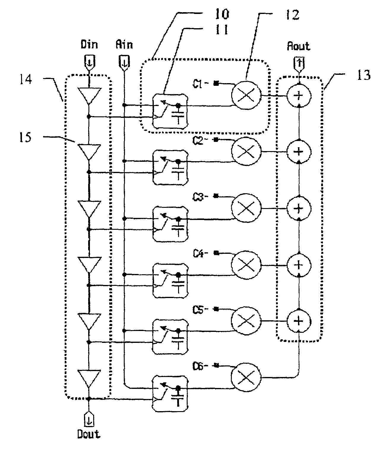
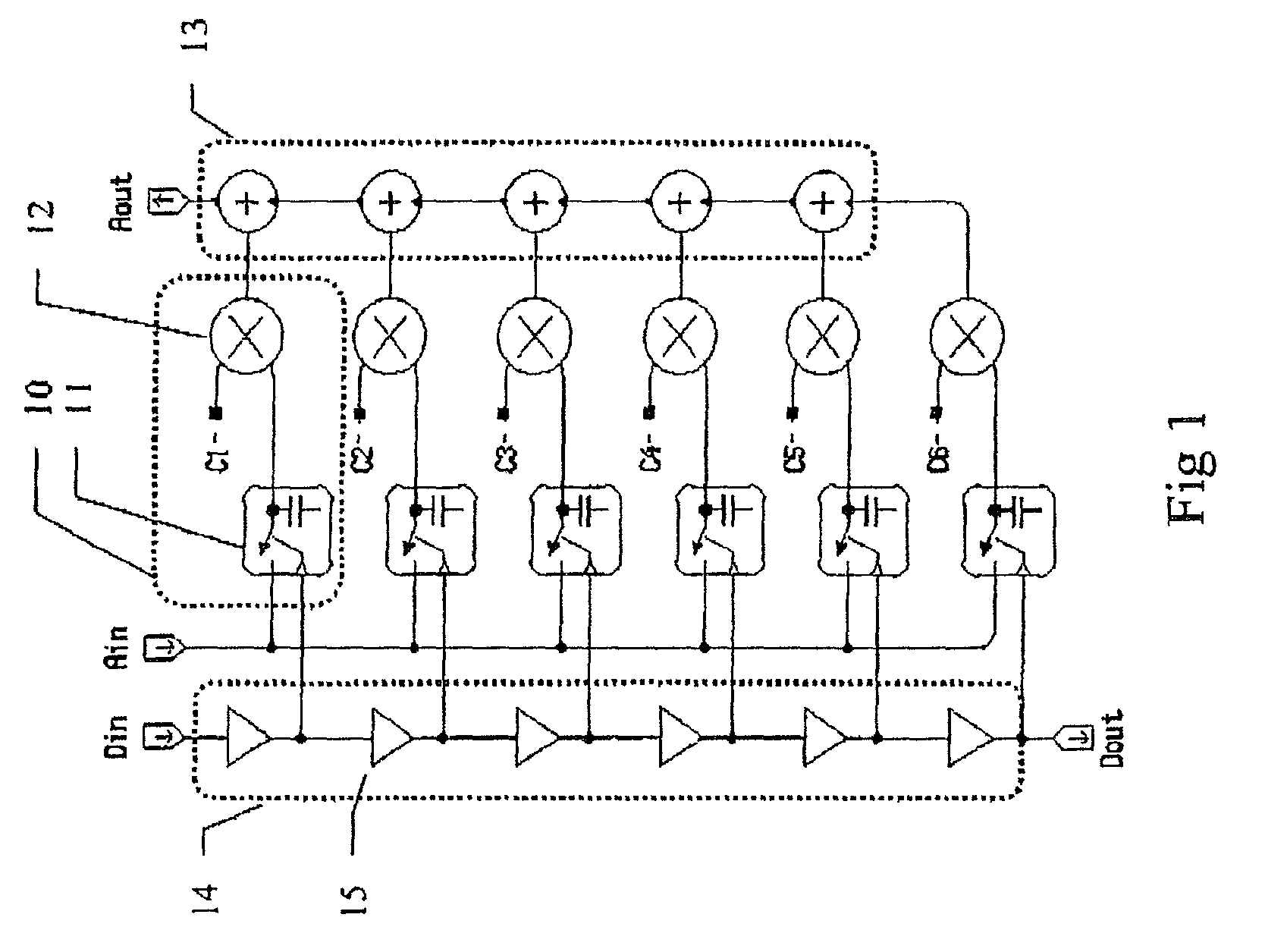
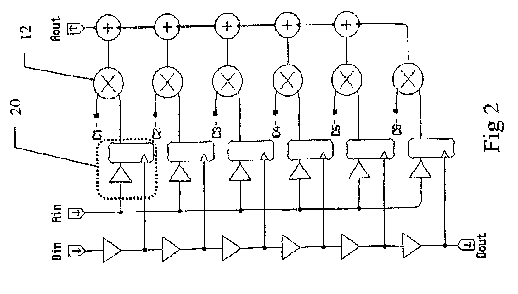
[0039]The term f is the frequency of interest and the constant k depends upon the time interval between samples n. Two summations are needed: one representing the real and one the imaginary term in the integral. Xn is the n th sample of X. The summations are examples of the following sequence:

+Xn·sn+Xn+1·sn+1+Xn+2·sn+2 +Xn+3·sn+3+

where the sn are the fixed (invariant for a particular receiver frequency) sine and cosine terms and the Xn are the samples of the input signal from the radio antenna.

[0040]In prior art f...


PUM


Abstract

An electronic filter operates as a correlator that provides a discrete approximation of an analog signal. The analog to digital conversion is integrated directly approximation calculation. An array of sample and hold circuits or single bit comparators provide outputs to a series of multipliers, the other input of which is a coefficient value of a Fourier series approximation of the desired frequency response. Each of the sample and hold circuits samples sequentially in time and holds its sample until the next cycle. Thus the sample point rotates in time through the array and each new sample is multiplied by a different coefficient. The output of the multipliers is summed for evaluation.

Description

RELATED APPLICATIONS[0001]This application claims priority to Canadian Patent Application Serial No. 2,332,609, entitled High Speed Filter, filed Jan. 29, 2001.TECHNICAL FIELD OF THE INVENTION[0002]This invention relates to signal processing and in particular to a method and circuit for implementing an electronic filter.BACKGROUND OF THE INVENTION[0003]A known class of DSP filters operate by successively sampling the input signal and implementing the following discrete Fourier approximation:[0004]R=Ss·Ss+Sc·Sc⁢⁢whereSs=∑n=0m⁢⁢Xn·sin⁡(f·k·n),Sc=∑n=0m⁢⁢Xn·cos⁡(f·k·n)[0005]One such type of filter is known as a Finite Impulse Response (FIR) filter. The input signal is sampled, and each sample is fed in turn to a series of multipliers the other input to which is one of the Fourier coefficients or its analog. As one sample is shifted out of a first multiplier to the next one, the next sample in time is presented to the first multiplier, and so on.[0006]While the foregoing approaches have ...

Claims


Application Information

Patent Timeline
Patent Type & Authority Patents(United States)
IPC IPC(8): G06G1/02H03M1/12G06G7/19H03H17/06
CPCH03H15/00G06G7/1928
Inventor MALLINSON, ANDREW MARTIN
Owner ESS TECHNOLOGY
Why Eureka
Try Eureka