
Decimating down converter and related methods

a converter and converter technology, applied in the direction of code conversion, transmission, electrical equipment, etc., can solve the problems of considerable power consumption and large digital resources of functions

Active Publication Date: 2007-07-10
HARRIS GLOBAL COMM INC
View PDF7 Cites 5 Cited by
  • Summary
  • Abstract
  • Description
  • Claims
  • Application Information

AI Technical Summary

Benefits of technology

[0007]In view of the foregoing background, it is therefore an object of the present invention to provide a system or method as a low power approach for sampling and downconverting a frequency or phase modulated IF signal to baseband in an efficient manner.

Problems solved by technology

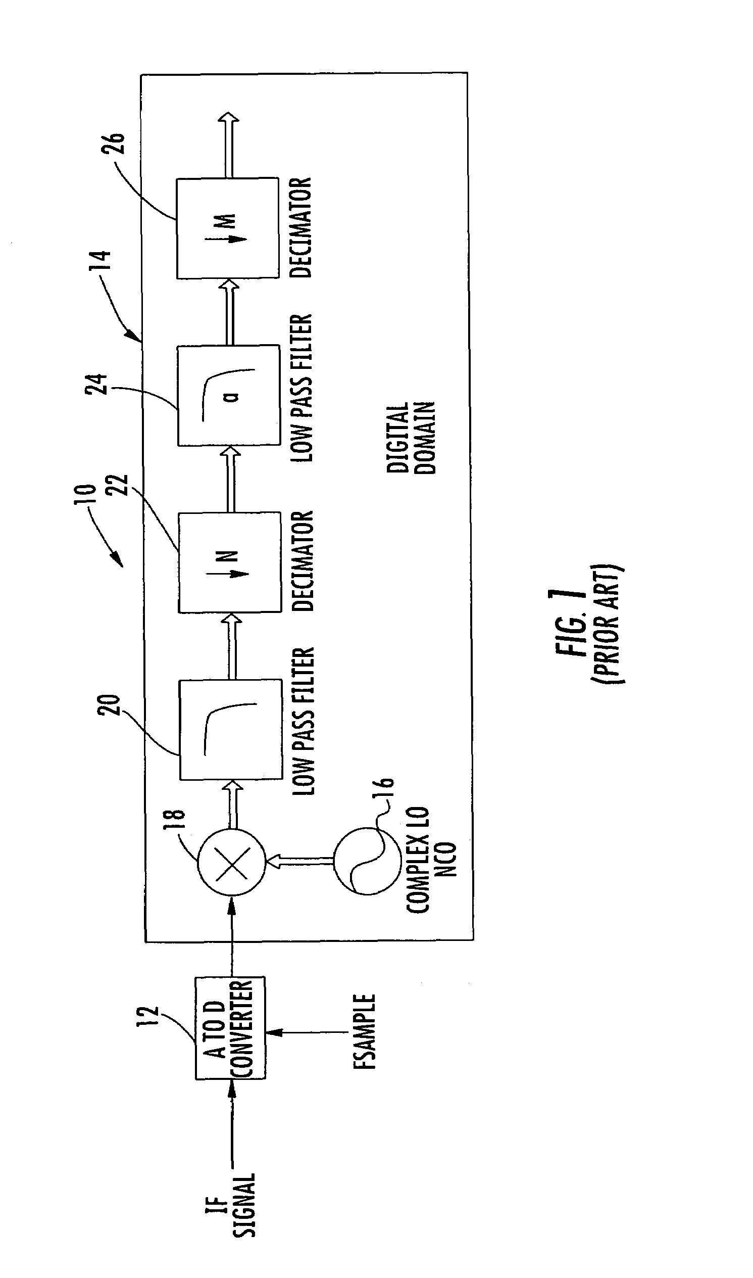
These functions can consume considerable digital resources and consume considerable power depending on their clock rates.

Method used


Image

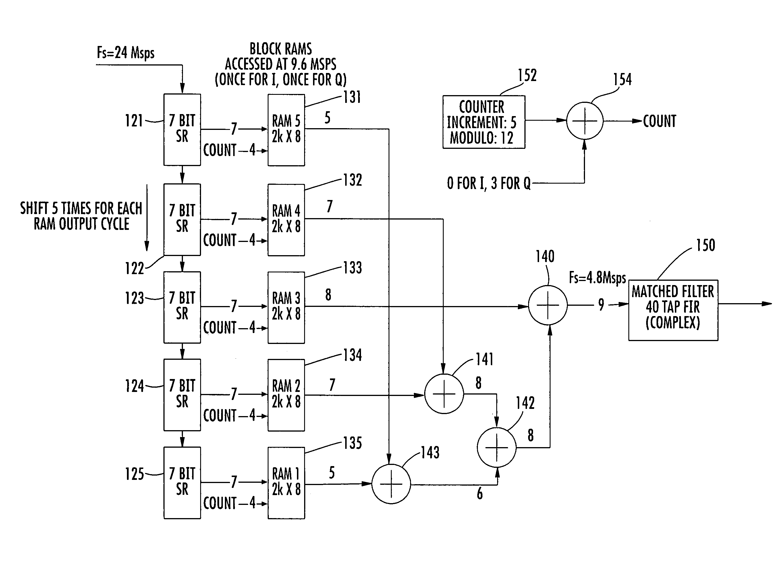
  • Decimating down converter and related methods
  • Decimating down converter and related methods
  • Decimating down converter and related methods

Examples


Embodiment Construction

[0020]The present invention will now be described more fully hereinafter with reference to the accompanying drawings, in which preferred embodiments of the invention are shown. This invention may, however, be embodied in many different forms and should not be construed as limited to the embodiments set forth herein. Rather, these embodiments are provided so that this disclosure will be thorough and complete, and will fully convey the scope of the invention to those skilled in the art. Like numbers refer to like elements throughout.

[0021]In accordance with one non-limiting example of the present invention, an intermediate frequency signal is reduced to a simple 1-bit representation, which is processed by undersampling the 1-bit signal. This undersampled signal is downconverted through a low pass filter and decimated using a series of memory (tables) containing precomputed values. The memory could be RAM, ROM or an ASIC. The description will proceed with a description of RAM relative ...


PUM


Abstract

A system of downconverting an intermediate frequency (IF) phase or frequency modulated signal to a digital baseband includes an N bit shift register circuit that receives a binary input as a 1-bit input sample data stream of an IF signal. A decimation circuit includes a memory and receives data from the N bit shift register circuit and stores N 1-bit binary samples as address bits and performs decimation, downconversion and filtering by accessing memory values at a predetermined rate.

Description

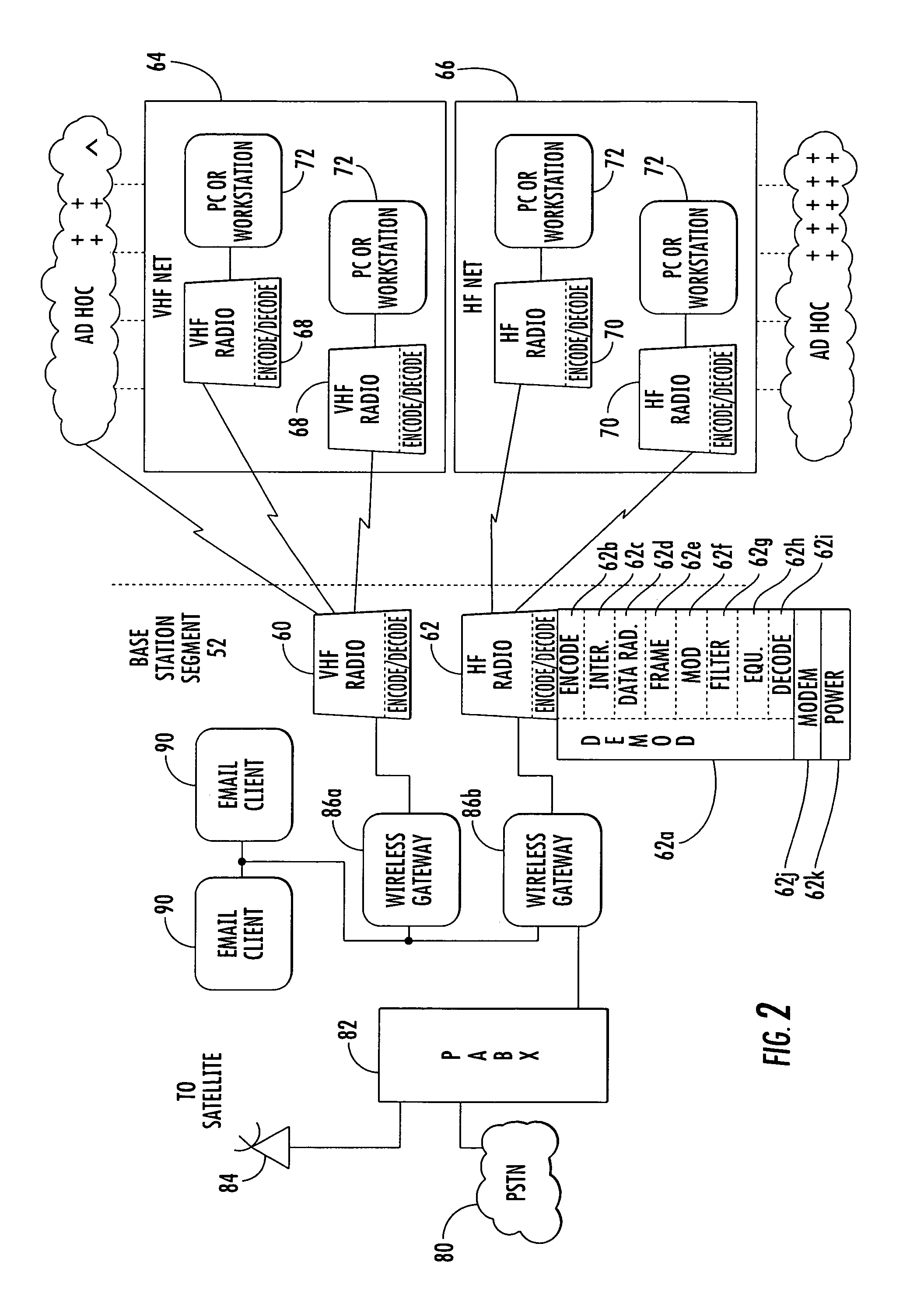
FIELD OF THE INVENTION[0001]The present invention relates to converting intermediate frequency (IF) signals to digital baseband, and more particularly, the present invention relates to downconverting a frequency or phase modulated intermediate frequency signal to digital baseband.BACKGROUND OF THE INVENTION[0002]Some multi-band or other tactical radios operate in the high frequency (HF), very high frequency (VHF) (for satellite communications), and ultra high frequency (UHF) bands. The range of these multi-band tactical radios can operate over about 2.0 through about 512 MHz frequency range. Next generation radios will probably cover about 2.0 to about 2,000 MHz (or higher) to accommodate high data rate waveforms and less crowded frequency bands. This high frequency transmit mode is governed by standards such as MIL-STD-188-141B, while data modulation / demodulation is governed by standards such as MIL-STD-188-110B, the disclosures which are incorporated by reference in their entirety...

Claims


Application Information

Patent Timeline
Patent Type & Authority Patents(United States)
IPC IPC(8): H03M7/00
CPCH04B1/28
Inventor THOMPSON, MARK W.
Owner HARRIS GLOBAL COMM INC
Learn More