Conveyor roller assembly, conveyor roller insert and axle for conveyor roller

a technology of conveyor rollers and roller inserts, which is applied in the direction of conveyor parts, roller-ways, transportation and packaging, etc., can solve the problems of further wear and noise, wear and noise, and add to the wear on

Inactive Publication Date: 2006-04-18
SST CONVEYOR COMPONENTS INC
View PDF8 Cites 40 Cited by
  • Summary
  • Abstract
  • Description
  • Claims
  • Application Information

AI Technical Summary

Problems solved by technology

However, a disadvantage with such a conveyor rollers is that a loose fit between the protrusions and the mounting holes can enlarge due to wear over time to the point where the protrusions may rotate in their respective mounting holes, resulting in further wear and noise.
However, even when rollers having protrusions with eccentric shapes are used, some wear and noise results during use due to the continual vibration of the conveyor assembly.
Furthermore, over time, the edges of the protrusions and the mounting holes or slots can wear to the point where rotation of the protrusion in the hole becomes possible, further adding to the wear on, and early failure of, the rollers.
The repair work that is required to maintain these systems, especially when conveyor rollers wear out and fail prematurely, can be quite expensive both in labor and materials and production downtime.
However, with prior art rollers in which the mounting components are integral, the entire roller may have to be discarded despite the failure of only one mounting component.

Method used


Image

  • Conveyor roller assembly, conveyor roller insert and axle for conveyor roller
  • Conveyor roller assembly, conveyor roller insert and axle for conveyor roller
  • Conveyor roller assembly, conveyor roller insert and axle for conveyor roller

Examples


Embodiment Construction

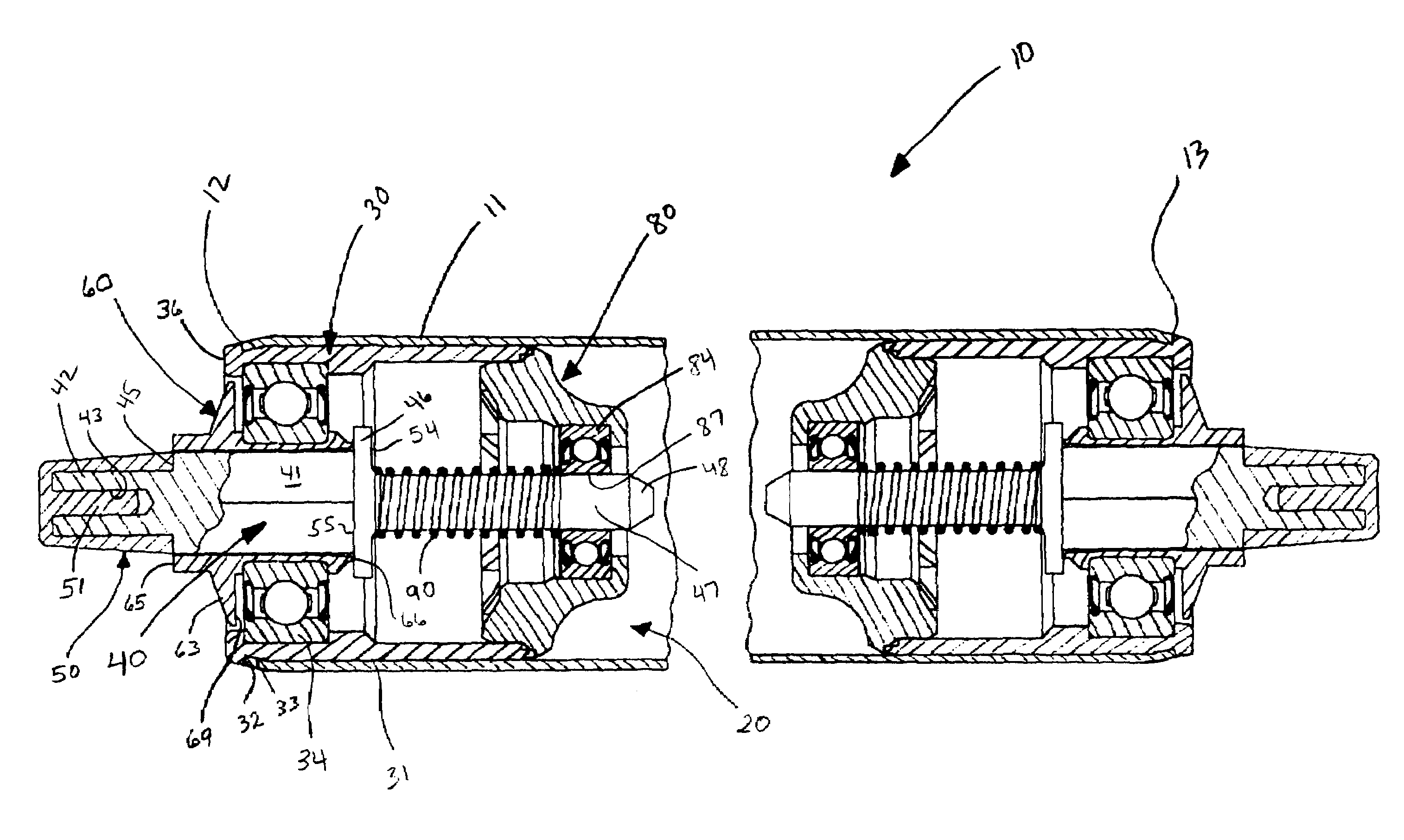
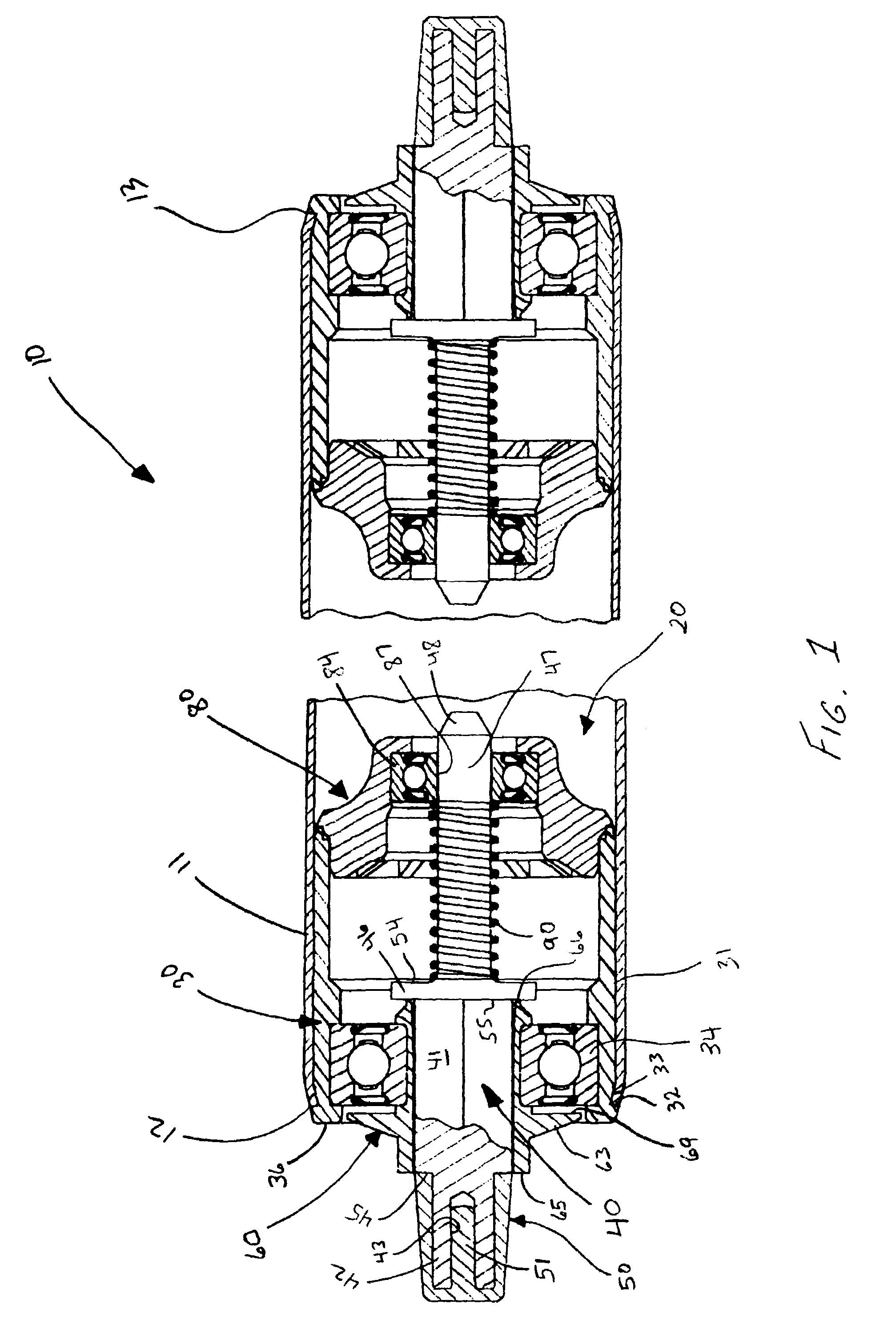
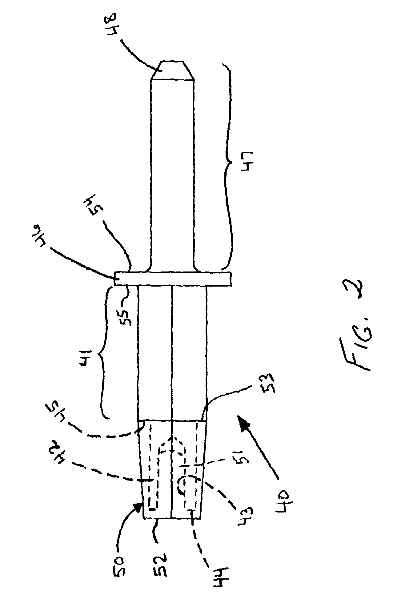
[0034]The present invention is directed to a conveyor roller assembly, a conveyor roller insert for a conveyor roller tube, as well as an axle for use in a conveyor roller. In particular embodiments, the outer end portion of the axle (i.e., the portion of the axle which engages the mounting hole in a conveyor frame) is replaceable and may have a surface hardness which is less than that of the inner portion of the axle.

[0035]For example, a removable end cap made from a polymeric material (e.g., an elastomer such as polyurethane or a thermoplastic such as polypropylene or nylon) is secured on an outer tip portion of a metal axle. Since this polymeric end cap is positioned within the mounting hole of the conveyor frame rather than the metal portion of the axle, embodiments of the present invention result in significant reduction in vibration and noise, as well as reduced wear of the mounting holes of the conveyor frame. In addition, since the end cap may be easily replaceable, embodime...


PUM


Abstract

A roller insert for a conveyor roller tube including a cartridge having inner and outer ends and configured to be inserted into an end of a conveyor roller tube; a stub axle positioned within the cartridge, the stub axle including an elongate body portion, a cylindrical tip portion extending away from the body portion, and an end cap having distal and proximal ends and a hardness less than that of the tip portion, the end cap threadingly secured on the cylindrical tip portion; and at least one bearing mounted within the cartridge and supporting the axle such that the cartridge is rotatable with respect to the axle and the axle is slidable with respect to the bearing; wherein the axle is biased outwardly from the cartridge such that the end cap projects outwardly from the cartridge outer end. A conveyor roller and an axle for a conveyor roller are also provided.

Description

FIELD OF THE INVENTION[0001]The present invention relates to the field of conveyor rollers and, more particularly, to conveyor rollers having stub shafts, conveyor roller inserts for mounting conveyor rollers to a support frames. and conveyor roller axles.BACKGROUND OF THE INVENTION[0002]Conveyor systems utilizing rollers are widely used in a variety of industrial applications. In a typical configuration, a plurality of closely spaced, freely-rotating conveyor rollers are mounted in parallel to an elongate support frame. The structure for mounting the rollers to the support frame is integral with the rollers. In some conveyor roller designs, inserts are mounted in each end of the roller tube and include protrusions projecting outwardly from the ends of the tube which are received within opposing pairs of mounting holes provided on the conveyor frame. Consequently, each conveyor roller assembly is independently attachable to and removable from the conveyor support frame.[0003]Such a ...

Claims


Application Information

Patent Timeline
Patent Type & Authority Patents(United States)
IPC IPC(8): B65G13/00B65G13/02B65G39/09
CPCB65G39/09
Inventor SCOTT, C. WINFIELD
Owner SST CONVEYOR COMPONENTS INC
Why Eureka
Try Eureka